EasyManua.ls Logo

Ingersoll-Rand 4WCC4060A1000A User Manual

Ingersoll-Rand 4WCC4060A1000A
24 pages
To Next Page IconTo Next Page
Page #1 background imageLoading...
Page #1 background image
SSAAFFEETTYY WWAARRNNIINNGG
Only qualified personnel should install and service the equipment. The installation, starting up, and servicing of heating, ventilating, and
air-conditioning equipment can be hazardous and requires specific knowledge and training. Improperly installed, adjusted or altered
equipment by an unqualified person could result in death or serious injury. When working on the equipment, observe all precautions in the
literature and on the tags, stickers, and labels that are attached to the equipment.
September 2018
1188--EEBB2299DD11--11FF--EENN
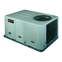
Single Packaged Heat Pump
14 SEER Convertible, 2 5 Ton
4WCC4024A1000A
4WCC4030A1000A
4WCC4036A1000A
4WCC4042A1000A
4WCC4048A1000A
4WCC4060A1000A
NNoottee:: “Graphics in this document are for representation only. Actual
model may differ in appearance.”
Installer’s Guide
Question and Answer IconNeed help?

Do you have a question about the Ingersoll-Rand 4WCC4060A1000A and is the answer not in the manual?

Ingersoll-Rand 4WCC4060A1000A Specifications

General IconGeneral
BrandIngersoll-Rand
Model4WCC4060A1000A
CategoryHeat Pump
LanguageEnglish

Summary

SAFETY SECTION

HAZARDOUS VOLTAGE!

Warning about potential death or severe injury from electrical hazards.

SAFETY AND ELECTRICAL HAZARD!

Caution for qualified personnel regarding electrical shock risks during servicing.

GROUNDING REQUIRED!

Importance of proper grounding to prevent equipment damage or personal injury.

UNIT CONTAINS R-410A REFRIGERANT!

Warning about R-410A refrigerant pressure and required service equipment.

SAFETY HAZARD!

Warning about severe injury or death from operating without access panels.

Step 4 - Unit Installation: Ground Level

Ground Level Installation

Instructions for installing the unit on a pad at ground level, including pad requirements and ductwork.

Step 4 - Unit Installation: Lifting and Rigging

Lifting and Rigging

Safety precautions and procedures for lifting and rigging the unit for installation.

Placing Unit on Mounting Curb

Instructions for correctly positioning and securing the unit onto the mounting curb.

Step 4 - Unit Installation: Rooftop Frame Mounting

Step 4 - Unit Installation: Diagrams and Tables

Step 4 - Unit Installation: Rooftop Frame Applications

Step 4 - Unit Installation: Ductwork and Drain Piping

Step 4 - Unit Installation: Filters and Power Wiring

Electrical Power Wiring

Guidelines for power supply, disconnect switch, over current protection, and conduit connection.

Step 4 - Unit Installation: Wiring Diagrams

Field Wiring Diagram

Detailed wiring diagrams for single power entry, economizer, and thermostat connections.

Control Wiring (Class II)

Instructions for low voltage control wiring, thermostat cable routing, and wire size recommendations.

Step 5 - Unit Startup

Voltage and Pressure Checks

Steps for checking operating voltage and refrigerant pressures to ensure correct operation.

Sequence of Operation: Maintenance

Service Maintenance

Recommended annual service checks by a qualified technician for optimal performance and safety.

Related product manuals