E2010
)$;
INGERSOLL RAND COMPANY
209 NORTH MAIN STREET -- BRYAN, OHIO 43506
OPERATOR’S MANUAL
6661AX-X-C
RELEASED: 9-11-89
REVISED:
(REV.
INCLUDING: OPERATION, INSTALLATION & MAINTENANCE
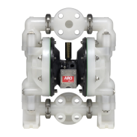
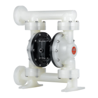
1” DIAPHRAGM PUMP
1:1 RATIO (NON-METALLIC)
READ THIS MANUAL CAREFULLY BEFORE INSTALLING,
OPERATING OR SERVICING THIS EQUIPMENT.
It is the responsibility of the employer to place this information in the hands of the operator. Keep for future reference.
SERVICE KITS
Refer to the Model Description Chart to match the pump material options.
637118-C for Air Section repair (see page 6).
637161-XX-C for Fluid Section repair (see page 4).
PUMP DATA
Models See Model Description Chart for “-XXX”.......
Pump Type Non-Metallic, Air Operated, Double Diaphragm...
Material See Model Description Chart.......
Weight 6661A3
-, 1AF-, 1AJ-, 1AL- 20.25 lbs (9.19 kgs)...
6661AP
-, 1AR-, 1AS-, 1AT- 20.25 lbs (9.19 kgs)..
6661A4
-, 1AG-, 1AK-, 1AN- 28.5 lbs (12.93 kgs)..
6661B3
-, 1BF-, 1BJ-, 1BL- 28.8 lbs (13.06 kgs)...
6661BP
-, 1BR-, 1BS-, 1BT- 28.8 lbs (13.06 kgs)..
6661B4
-, 1BG-, 1BK-, 1BN- 37 lbs (16.78 kgs)..
Maximum Air Inlet Pressure 120 p.s.i. (8.3 bar)........
Maximum Material Inlet Pressure 10 p.s.i. (0.69 bar)....
Maximum Outlet Pressure 120 p.s.i. (8.3 bar).........
Maximum Flow Rate
(flooded inlet) 47 g.p.m. (177.9 l.p.m.)....
Displacement / Cycle @ 100 p.s.i.g. 0.17 gal. (0.64 lit.)..
Maximum Particle Size (semi-solids) 1/8” dia. (3.2 mm)...
Maximum Temperature Limits
Polypropylene 35_ to 175_ F(2_ to 79_ C).....
PVDF (Kynar) 10_ to 200_ F(-12_ to 93_ C).....
Dimensional Data see page 8...............
Noise Level @ 70 p.s.i. - 60 c.p.m.{ 64.5db(A)|..
{ Tested with 93110 muffler installed.
| The pump sound pressure levels published here have been updated to an Equivalent
Continuous Sound Level (L
Aeq
) to meet the intent of ANSI S1.13-1971, CAGI-PNEU-
ROP S5.1 using four microphone locations.
NOTICE: All possible options are shown in the chart, however, certain
combinations may not be recommended, consult a representative or the
factory if you have questions concerning availability.
GENERAL DESCRIPTION
The ARO Diaphragm Pump offers high volume delivery even at low air
pressure and a broad range of material compatibility options available.
Refer to the model and option chart. ARO pumps feature stall resistant
design, modular air motor / fluid sections.
Air operated double diaphragm pumps utilize a pressure differential in
the air chambers to alternately create suction and positive fluid pressure
in the fluid chambers, ball checks insure a positive flow of fluid.
Pump cycling will begin as air pressure is applied and it will continue to
pump and keep up with the demand. It will build and maintain line pres-
sure and will stop cycling once maximum line pressure is reached (dis-
pensing device closed) and will resume pumping as needed.
6661X3-XXX-C
6661X4-XXX-C
6661XP-XXX-C
6661XF-XXX-C
6661XG-XXX-C
6661XR-XXX-C
6661XJ-XXX-C
6661XK-XXX-C
6661XL-XXX-C
6661XN-XXX-C
6661XS-XXX-C
6661XT-XXX-C
Figure 1
MODEL DESCRIPTION CHART
6661 X X -X X X -C
6661XX - X X X -C
637161 - X X - C
DIAPHRAGMBALL
FLUID SECTION SERVICE KIT SELECTION
EXAMPLE: MODEL # 6661A3-311-C
FLUID SECTION SERVICE KIT # 637161-11-C
SEAT MATERIAL
2 - 316 Stainless Steel 4 - PVDF (Kynar)
3 - Polypropylene 8 - Hard 440 Stainless Steel
DIAPHRAGM MATERIAL
1 - Neoprene 3 - Viton 9 - HytrelR
2 - Nitrile 5 - E.P.R. B - Santoprene
4 - PTFE / Santoprene M - Medical Grade Santoprene
CENTER BODY MATERIAL
A - Aluminum B - Cast Iron
FLUID CAP / MANIFOLD MATERIAL
3 - Colorless Polypropylene flange (3-piece manifold)
4 - PVDF (Kynar
R) flange (3-piece manifold)
F - Colorless Polypropylene flange (one piece manifold)
G - PVDF (Kynar) flange (one piece manifold)
J - Colorless Polypropylene, N.P.T. (one piece manifold)
K - PVDF (Kynar), N.P.T. (one piece manifold)
L - Colorless Polypropylene, B.S.P. (one piece manifold)
N - PVDF (Kynar), B.S.P. (one piece manifold)
P - Gray Polypropylene flange (3-piece manifold)
R - Gray Polypropylene flange (one piece manifold)
S - Gray Polypropylene, N.P.T. (one piece manifold)
T - Gray Polypropylene, B.S.P. (one piece manifold)
BALL MATERIAL
1 - Neoprene 8 - Polyurethane
2 - Nitrile A - 316 Stainless Steel
3 - Viton
R E - SantopreneR
4 - PTFE M - Medical Grade Santoprene
5 - E.P.R.
www.ingersollrandproducts.com
CCN 81660326
11-13-10
U)