A
Ashley BartlettAug 20, 2025
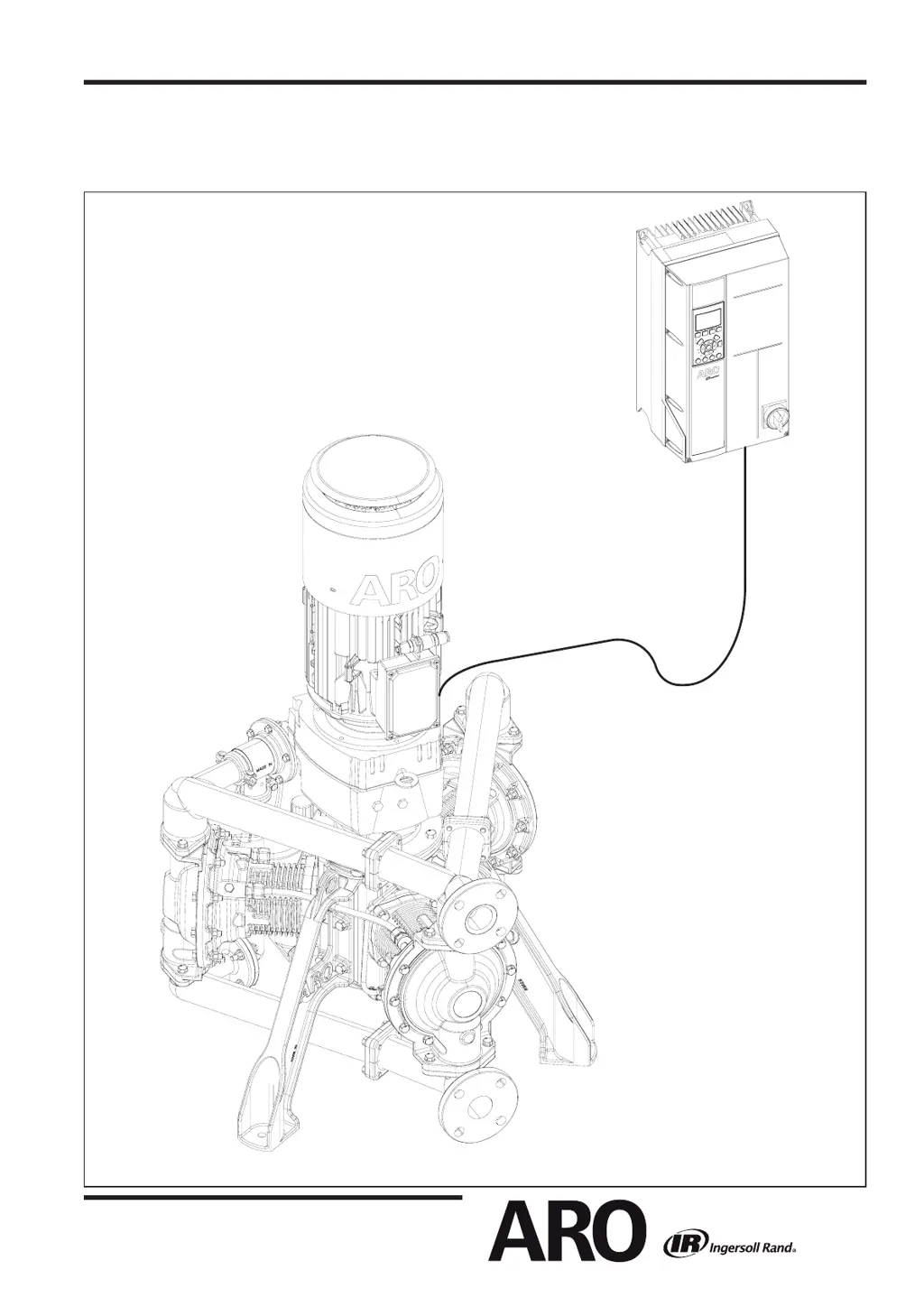
Why my Ingersoll-Rand Water Pump will not operate?
- DDennis MooreAug 20, 2025
If your Ingersoll-Rand Water Pump is not operating, it could be due to several reasons: * Improper power, sensor, or control wiring. Ensure wiring is done according to the manual's instructions. * The Smart Setup wasn't completed at VFD startup. Complete the Smart Setup in the Quick Menu, Selection §4. * A VFD Alarm. Check the VFD manual section 7.4 for a list of alarm codes. * The torque limit is set too low. Increase VFD parameter 4-16, but do not exceed 100%. * Crankshaft bearing failure. Replace the pump crankcase.