This document is an operator's manual for Ingersoll Rand Direct Expansion Compressed Air Dryers, specifically for 60 Hz dryers (G version). It covers models from D12IN-A to D950IN-A.
Function Description
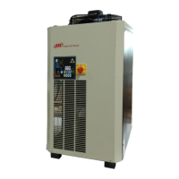
Ingersoll Rand refrigerated air dryers are designed to remove moisture from compressed air, which is detrimental to pneumatic appliances, controls, instruments, machinery, and tools. The drying process involves two stages within a patented aluminum heat exchanger:
- Air/Air Sector: Compressed inlet air is pre-cooled by the colder compressed air exiting the condensate separator.
- Refrigerant/Air Sector: The air temperature is further lowered to the dew point.
During these stages, oil and water vapors in the compressed air condense into liquid, which is then separated in the condensate separator and drained by an automatic drain. The cold, dried air then re-enters the air/air exchanger, where it is reheated by the incoming hot air. This process recovers energy and reduces the relative humidity of the outgoing air. These dryers are suitable for various pneumatic systems requiring dry air.
Important Technical Specifications
The manual provides detailed technical specifications for various models, including:
Air Flow Rate:
- D12IN-A to D480IN-A: Ranges from 12 m³/h (7 CFM) for D12IN-A to 480 m³/h (280 CFM) for D480IN-A.
- D600IN-A to D950IN-A: Ranges from 600 m³/h (353 CFM) for D600IN-A to 950 m³/h (559 CFM) for D950IN-A.
Power Supply:
- D12IN-A to D480IN-A: 230V/1Ph/60Hz.
- D600IN-A: 230V/1Ph/60Hz or 220V/1Ph/60Hz.
- D780IN-A to D950IN-A: 380V/3Ph/60Hz or 460V/3Ph/60Hz.
Compressor (1M1):
- HP: Varies from 1/10 HP (D12IN-A) to 1.1/2 HP (D480IN-A) for single-phase models.
- Max kW: Ranges from 0.19 kW (D12IN-A) to 2.79 kW (D480IN-A) for single-phase models.
- RLA: Ranges from 0.83 A (D12IN-A) to 8.7 A (D480IN-A) for single-phase models.
- For D600IN-A to D950IN-A (three-phase): Max kW ranges from 3.53 kW to 4.11 kW, and RLA ranges from 3.8 A to 4.33 A.
Fan Motor (1M2):
- HP: Varies from 1/120 HP (D12IN-A) to 1/4 HP (D480IN-A) for single-phase models.
- RLA: Ranges from 0.24 A (D12IN-A) to 0.83 A (D480IN-A) for single-phase models.
- For D600IN-A to D950IN-A (three-phase): RLA ranges from 0.58 A to 0.97 A.
Total Current (TOTAL A):
- Ranges from 1.4 A (D12IN-A) to 14.4 A (D480IN-A) for single-phase models.
- Ranges from 7.1 A to 7.2 A for three-phase models.
Connection (BSP):
- Ranges from 3/8" (D12IN-A) to 11/2" (D480IN-A) for single-phase models.
- 2" for D600IN-A to D950IN-A.
Operating Conditions:
- Air T (Inlet Air Temperature): 35°C (95°F).
- Air T Max (Max Inlet Air Temperature): 60°C (140°F).
- Amb T (Ambient Temperature): 25°C (77°F).
- Amb T Min-Max (Min-Max Ambient Temperature): 50°C (122°F).
- Press W (Working Pressure): 7 bar (100 psi).
- Air Press Max (Max Air Pressure): 14 bar (203 psi) for D12IN-A to D480IN-A; 13 bar (188 psi) for D780IN-A to D950IN-A.
- Dew Point: 7°C (45°F) for D12IN-A to D480IN-A (Class 5); 3°C (37°F) for D600IN-A to D950IN-A (Class 4).
Refrigerant:
- Type: R134a for D12IN-A to D600IN-A; R407C for D240IN-A to D950IN-A.
- Charge: Varies by model, e.g., 0.17 kg (0.37 LB) for D12IN-A (R134a), 2.15 kg (4.74 LB) for D780IN-A (R407C).
Weight:
- Ranges from 17 kg (37.48 LB) for D12IN-A to 110 kg (242.50 LB) for D480IN-A.
- Ranges from 120 kg (264.6 LB) for D600IN-A to 150 kg (330.7 LB) for D950IN-A.
Evaporation Temperature (EVAP, TEMP):
- 3-5°C (37-41°F) for R134a models.
- 1-2°C (34-35.5°F) for R407C models.
Suction Temperature (SUCTION TEMP):
- 4-6°C (39-43°F) for R134a models.
- 4-10°C (39-50°F) for R407C models.
Discharge Pressure (DISCH, PRESS):
- 12-16 barg (170-230 psig) for R134a models.
- 13-18 barg (188-261 psig) for R407C models.
Noise Level (DB(A)): < 70 dB(A) for most models, 76 dB(A) for D780IN-A and D950IN-A (380V/3Ph/60Hz).
Correction Factors: The manual includes tables for correction factors based on working pressure, ambient temperature, and inlet air temperature to calculate the real flow rate or select a suitable dryer.
Usage Features
- Control Panel: Equipped with ON/OFF switch, condensate discharge parameters programming, and anomaly warning indicators.
- Display Indications: The controller displays current dew point and blinks messages for anomalies like high dew point (HtA, Ht2), probe issues (PF1), energy saving mode (ESA, ES2), and repeated alarms (ASt).
- Remote Signaling Alarm: A dry contact is available for remote alarm signals, normally open, closing when an alarm is detected.
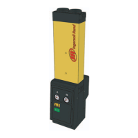
- Zero Drain Option: An electronic drain discharger that eliminates condensate without wasting compressed air, using an electronic sensor to detect condensate levels and manage drainage. It includes a remote alarm connection.
- Safety Features: The dryer is equipped with all necessary control, safety, and adjustment devices. Overload within operative limits will not affect safety.
- Installation: Must be installed in a vertical position, protected from atmospheric agents, on a flat base, in a clean area without forced air draft, and with sufficient clearance for cooling and maintenance. A prefilter (at least 10 micron) is mandatory.
- Start-up: Requires ensuring all parameters match nominal data, checking for proper installation, activating power supply, waiting for the machine to reach operating parameters, and verifying condensate drain and pipe connections. For D780-950IN-A models, a main power switch must be turned on, and the dryer must be allowed to run for 8 hours before starting.
Maintenance Features
- Qualified Personnel: All installation, maintenance, and control operations must be performed by qualified and certified personnel.
- Safety Precautions: Before any maintenance, disconnect electrical supply, discharge air pressure, and refer to the manual. Do not service while operational, remove parts under pressure, or remove refrigeration system parts without proper refrigerant removal.
- Weekly/Every 40 Hours:
- Verify temperature on the control panel display.
- Visually check if condensate drains regularly.
- Monthly/Every 200 Hours:
- Clean the condenser with compressed air.
- Check dryer operation.
- Check and replace filters as needed.
- Yearly/Every 2000 Hours:
- Check and replace flexible tube for condensate drainage if damaged.
- Check if all connecting pipes are tightened and fixed.
- Check dryer operation.
- Every 24 Months/Every 4000 Hours (D600IN-A + D950IN-A):
- Replace the fan pressure switch.
- Troubleshooting: The manual provides a detailed troubleshooting guide for various issues, including blank control panel, condensate drain malfunction, high dew point, low pressure, and electrical problems. It emphasizes contacting a refrigeration engineer for refrigerating circuit maintenance.
- Zero Drain Maintenance: The Service Unit of the Zero Drain is recommended to be changed annually. Instructions are provided for disconnecting the dryer, removing the electrical connector, unscrewing the unit, removing the Service Unit, cleaning the filter mesh, replacing the Service Unit, and reassembling. A TEST button is available to clean the mesh filter if the discharger malfunctions.
- Decommissioning: In case of necessity, the machine and its packaging must be decommissioned in compliance with local rules. Special attention must be paid to the refrigerant, which contains lubricating oil, and a waste disposal and recycling facility must be contacted.
Warranty: The equipment is warranted against defects in material and workmanship for 12 months from operation date or 18 months from shipment, whichever comes first. The warranty requires proper storage, installation, maintenance, and operation according to good industry practices and company recommendations. Corrosion, erosion, and normal wear and tear are excluded.