Do you have a question about the Ingersoll-Rand EP 20 SE and is the answer not in the manual?
Details warranty terms for defects in material and workmanship for the compressor.
Specifies exclusions and limitations on company liability for damages and losses.
Provides warranty terms for the airend component when specific coolant is used.
Emphasizes reading all manual instructions before installation and operation.
Details hazards and precautions for electrical, pressure, and mechanical safety.
Instructions for inspecting the compressor upon delivery for any signs of damage.
Guidance on safely unpacking and handling the compressor unit from its base.
Lists the basic tools required for removing the compressor unit from its wooden skid.
Requirements for adequate ventilation to prevent compressor overheating due to heat production.
Guidance on selecting and preparing a suitable level floor for compressor installation.
Recommendations for safe and effective piping installation, including material choices.
Description of the emergency stop button function and reset procedure.
Details the functions of the START, DISPLAY SELECT, SET, and ARROWS buttons.
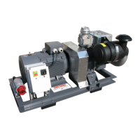
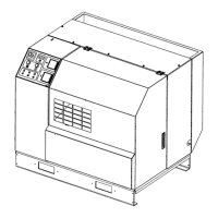
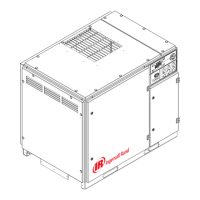
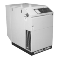
Overview of the SE compressor package components and optional accessories.
Explains coolant flow, thermostatic control, and the hydraulic-type full-flow filter.
Details the components of the compressed air system, from inlet to aftercooler.
Specifies recommended maintenance intervals based on running hours or time.
Method for adjusting belt tension using a gauge and specific deflection force values.
Step-by-step guide for replacing the two lip type shaft seals on the compressor.
Details lubrication intervals and amounts for induction-type squirrel cage motors.
Details the remote start/stop option for controlling the compressor from a remote station.
Describes the combined option for remote control and automatic restart after power interruption.
Diagram showing the electrical wiring for a full voltage starter system.
Diagram illustrating the electrical wiring for a star-delta starter system.
| Power | 2 HP |
|---|---|
| Pump Type | Oil-Free |
| Tank Size | 20 Gallon |
| Noise Level | 75 dB |
| Phase | Single |