Do you have a question about the Ingersoll-Rand SSR-2000 and is the answer not in the manual?
Outlines the purpose of the manual in assisting operators with understanding and maintaining the compressor.
Prompts for recording unit model and serial numbers for reference.
Warns about high voltage and the necessity of electrical isolation and grounding for safe operation.
Covers risks from hot liquids/air, operating pressure limits, safe mechanical work, and operational guidelines.
Addresses potential issues with compressor lubricants entering plant air and hazardous filter bowls.
Explains the data plate details like rated operating pressure and motor characteristics.
Critical warning about the need for specialized equipment for breathing air and user liability.
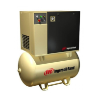
Lists components and explains the mechanism of compression using helical rotors.
Describes the path of air and coolant through separation and aftercooling for water vapor removal.
Covers load control, safety shutdowns, air and coolant filtration, and optional features.
Describes how air is drawn into rotor pockets and trapped as rotors rotate.
Explains the compression phase where coolant is injected for heat absorption and sealing.
Details the discharge of compressed air and coolant mixture to the receiver tank.
Explains the positive-displacement pump and the thermostatic valve regulating coolant flow to the cooler.
Describes how filtered coolant is distributed to various points for lubrication and capacity control.
Explains the role of the receiver tank and its specially designed internals for coolant separation.
Describes how internal baffles and inertial action collect coolant droplets from the air stream.
Specifies design temperatures, cooler assembly, and fan motor details for aircooled units.
Details design temperatures, cooling water requirements, and thermostatic control for watercooled units.
Explains the function of aftercoolers in reducing water vapor condensation for both air and watercooled types.
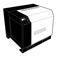
Instructions for inspecting the unit for transit damage and proper handling during unpacking.
Guidance on foundation preparation, plant location, and necessary clearances for maintenance access.
Covers condensate drain piping and recommendations for integrating with the plant air system.
Provides a table of dimensions for 50Hz air-cooled international units based on model designation.
Presents dimensions in inches for 60Hz domestic and international air-cooled units.
Describes the system's reliance on solid-state components and lists key electrical parts like starters and control transformers.
Identifies major components located within the electrical starter box using numbered labels.
Explains how to achieve an unloaded start using the No Load selector and inlet valve positioner.
Details the automatic sequence for a Star-Delta starter, including timer functions and contactor engagement.
Describes the sequence for a full voltage starter and the procedure for loading the compressor.
Provides a table for connecting the universal control transformer based on primary voltage and frequency.
Illustrates the physical terminals on the transformer for correct wiring.
Lists and defines abbreviations for various electrical components used in the manual.
Details the function and color of each indicating light on the compressor's control panel.
Identifies optional equipment modules such as annunciators and automatic control selectors.
Explains the discharge temperature gauge and the dual air pressure gauge for receiver and line pressure.
Describes the Power On light and the Start-Stop push buttons for compressor control.
Details the function of the hour meter for maintenance scheduling and selector switches for control modes.
Explains the coolant and air filter maintenance indicator lights and their function.
Describes the high-pressure relief valve on the receiver and the coolant pump relief valve.
Details the on-off line control method for managing compressor output based on plant air pressure.
Explains how upper range modulation adjusts inlet air flow to match varying air demands.
Describes the optional system for automatic compressor shutdown and restart based on low demand periods.
Explains the ACS function in monitoring air demand and selecting the most efficient control mode automatically.
Step-by-step guide to setting the inlet air control valve and its lever arm.
Instructions for adjusting the linkage of the inlet valve positioner to ensure proper valve operation.
Procedures for setting the modulator and verifying the pressure switch operation for capacity control.
Procedure for setting the receiver pressure by adjusting the closing travel stop after other settings are confirmed.
Detailed steps for initial inspection, electrical verification, fluid checks, and motor rotation confirmation.
Specific instructions for starting water-cooled units, including coolant flow and level checks.
Describes the coolant's functions, properties, and recommended change intervals for optimal performance.
Explains the filter type, micron rating, bypass valve, and the maintenance indicator for the coolant filter.
Outlines the procedure for regularly checking the high air temperature shutdown switch.
Describes procedures for maintaining motor bearings on units intended for extended storage.
Provides recommendations for preparing units for long-term storage, including vapor space inhibitor management.
Lists troubleshooting steps for a compressor that will not start, covering electrical and control circuit checks.
Addresses causes for reduced capacity, such as filter issues, and factors leading to compressor overtemperature.
Explains potential reasons for high coolant-lubricant consumption, including separator element faults.
Procedure for testing the safety shutdown warning lights on the instrument panel for proper function.
Details the replacement intervals and procedures for coolant and air filter elements.
Step-by-step guide for draining and refilling the coolant-lubricant system, including filter replacement.
Outlines the procedure for replacing the coolant-lubricant separator element based on differential pressure or time.
Provides guidance on relubrication intervals for drive motor bearings based on motor size and operating conditions.
Details the procedure for relubricating motor bearings and specifies the amount of grease required based on shaft diameter.
| Type | Rotary Screw |
|---|---|
| Phase | 3 |
| CFM @ Full Load | 1050 CFM |
| Air Delivery | 1050 CFM |
| Voltage | 460 V |
| Drive Type | Direct Drive |
| Cooling Method | Air Cooled |