03540598_ed12 5
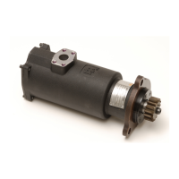
Mounting Dimensions ST900 Turbine Starter (Inertia)
1/4” Pipe Plug in Housing Inlet Boss
can be removed and Gage installed to
check supply pressure to Starter. Before
re-installing Plug, clean Threads and apply
Pipe Thread Sealant (IR No. SMB-441 or
equiv.) to prevent leakage.
“0”
“1”
Ø 193.00
“2”
175.00
(6.89”)
“3”
4,8 mm Hex. Head Bolts, allow rotation
of Inlet in 4 positions when changing Inlet
orientation do not rotate Intermediate
Gear Case. Intermediate Gear Case is timed
with the Oset Gear Case.
1. The Splash Deector Assembly must be removed
for accessing the 1/4” Hole Drive Barring Hole or
when installing a Piped away Exhaust.
2. Before removing the Hex. Plug the Starter must be
reasonably level to prevent draining the Oil from
the Gear Case.
3. When the Hex. Plug is removed a slight amount of Oil
may leak from the Hole. (this is normal).
4. Before reassembly clean all Oil from the Threads and apply
Pipe Thread Sealant (IR no. SMB-441 or equivalant)
to prevent Oil leakage.
5. Torque to 10-15 LB.-FT.
Splash Deector
86.00
(3.36”)
117.00
(4.61”)
158.28
(6.23”)
Over ST700-166
Flange
Standard Inlet Flange Kit ST700-K166
(includes mounting hardware)
69.80
(2.75”)
Cover
Ø
134.00
(5.28”)
4” NPT for Piped Exhaust when
using Piped Exhaust, replace Splash
Deector Assembly with Pipe Plug supplied with Starter.
Motor
Housing
Inlet Boss
35.70
(1.41”)
130.30
(5.13”)
85.85
(3.38”)
9.65
(0.38”)
12.70
(0.50”)
85.73
(3.38”)
22.35
(0.88”)
50.80
(2.00”)
46.00
(1.81”)
152.00
(5.98”)
110.34
(4.34”)
173.34
(6.82”)
Ø
1.50” type J518C
Flange
1/2” - 13 UNC 19.1
deep-4 places (0.75”)
442.7
(17.43”)
To Splash Deector (during operation)
426.8
421.8
(16.8”
16.6”)
318.5
313.7
(12.54”
12.35”)
R
71.00
(2.80”)
Oset
Gear
Case
Drive
Housing
Ø
92.01
(3.62”)
137.50
(5.41”)
73.15
(2.88”)
Ø
Intermediate Gear Case
Orientation Options
Inlet
Drive Housing
4 @ 90°
16 @ 22 1/2°
Ring Gear Face
Mesh
Pilot
Ø
16.7
(0.66”)
Ø
3 - Places
7˚30’
P
A
B
C
D
E
F
G
H
I
J
K
L
M
N
O
120˚ typ.
R
Reference Hole for
Orientation Code
Left Hand
Rotation
Right Hand
Rotation
Notes:
1. Starters should be installed on the Engine
with the Exhaust pointed down.
2. These Models are not approved for applications
where the Starter is exposed to the Transmission Fluid.
3. Drive Housing Orientation Code is based on position
of Mounting Hole opposite the Pinion opening.
4. Standard orientation shown 02N with Exhaust Elbow will be
shipped unless otherwise specied.
5. Please read the instructions before attempting
to reorient.
6. Starter weight = 68 LBS (30.8 Kg.)
7. All dimensions are for the reference only. Installer should verify
mounting requirement prior to nal installation.
Dual
Dimensions
mm
(inch)
- Model Coding -
ST9
00
G
D
I
03
R
31
0
Size Starter
Percent Arc
Gear Ratio
Type of Drive Housing
Drive Housing
Orientation Code
Inlet
Pinion
Rotation
Drive
Type Drive Flange
Gas Operation
B
Type Gear Case
N
(Dwg. TPA1503)
Piping Diagram with Engine prelube system for a standard high pressure system when supply pressure is over
pressure rating of Starter.
Relay Valve 1 1/2”
SRV150
JIC 37° Adapter
1 1/2” NPT
JIC 37° Adapter 1 1/4” NPT
SS350-MC4
JIC 37° Adapter 1 1/4” NPT
SS350-MC4
Starter Control Valve
SMB-618 (Brass/Air)
SMBG-618 (Chrome/Gas)
1 1/2” Hose
Inlet Flange Kit
ST700-K166
1/4” NPT pressure measuring
port operating pressure not
to exceed max. pressure rating
stamped on Starter Nameplate.
Exhaust
Drive Housing
Vent Plug 1/8” NPT
#4 Hose (1/4”)
#4 Hose (1/4”)
#4 Hose (1/4”)
#4 Hose (1/4”)
To Prelube
Pump
Air Presssure Gage
150BMP - 1064L
(Air only)
1 1/2” Pipe
Oil Pressure Sensing Valve
ST900-267 Strainer
Relief Valve set at 15 psi
above Regulator setting
For Gas operation, the
Relief Valve Outlet must
be piped away to a safe
location.
High Pressure Supply
Set pressure Regulator to ensure
pressure at Starter does not exceed
Starter pressure rating during operation.
Note:
Use Sealant on all the
pipe connections.
SMB-441
For Natural Gas operation, Starter Main Exhaust must be piped away.
To pipe the Drive Housing Vent, Remove the Drive Housing Plug
and replace it with a suitable Tubing Line. The tubing must vent at a safe
location and must not be interconnected with any other Exhaust Lines
which might introduce a back pressure on the Drive Housing Vent.
(Dwg. TPA1448)
 Loading...


