4 03540598_ed12
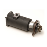
Mounting Dimensions (Pre-Engaged) for Series ST900 Starters
1/4” Pipe Plug in Housing Inlet Boss can be removed
and Gauge installed to check supply pressure to
Starter. Before re-installing Plug, clean threads and
apply Pipe Thread Sealant (IR no. SMB-441 or equiv.)
to prevent leakage
Inlet positions “0” thru “3”
(#0 shown)
Standard Inlet Flange Kit ST700-K166
(includes Mounting Hardware)
“0”
158.24 (6.23”)
over ST700-166
Flange
90°
“3”
“2”
“1”
175.00
(6.89”)
he Hex. Plug must be removed to access
the 1/4” Hex. Drive Barring Hole in the Rotor Shaft .
Before removing the Hex. Plug make certain the
Starter is level to prevent draining of oil from the
Gear Case. When the Hex. Plug is removed. A slight
amount of oil may leak from the Hole (this is normal).
117.00
(4.61”)
86.00
(3.39”)
135.42
(5.37”)
ø 156.0
(6.14”)
(4) Bolts allow rotation of inlet and elbow
in 4 positions. When changing oritation
do not rotate intermediate Gear Case.
Intermediate Gear Case is timed with
the oset Gear Case
Motor Housing
Intermediate Gear Case
69.80
(2.75”)
154.89
(6.10”)
35.70
(1.41”)
569.9
(22.44”)
597.1
(23.51”)
363.80
(14.32”)
223.80
(8.80”)
1/2” - 13 UNC th’d.
0.75” Deep - 4 Places
ø 38.1, 1.50” dia.
type J518C Flange
138.50
(5.45”)
10.00
(0.39”)
23.00
(0.91”)
R 76.00
(2.99”)
R 71.00
(2.80”)
Inlet Boss
Gear Case
Oset
85.73
(3.38”)
Drive Housing
160.50
(6.32”)
58.34
(2.30”)
50.80
(2.00”)
Flywheel Face
91.98
(3.62”)
Pilot dia.
28.50
Pinion travel
18.50
(0.73”)
Drive Housing Vent Plug
1/8” NPT
* *
1/4” NPT Control Port for
engaging Pinion.
Operating Pressure = 70 to 150 psig
(483 to 1034kPa)
Operating Pressure = 70 to 150 psig
(483 to 1034kPa)
1/4” NPT Control Port for actuation
of main air supply to Starter Motor
ø 16.60
(0.65”)
Holes mounting
unit; 3 Holes; SAE 3 Flange
7° 30’
Control Ports
Angle “A” thru “P”
(Angle “G” shown)
C
L
ø 137.50
(5.41”)
“A”
“B”
“C”
“D”
“E”
“F”
“G”
“H”
“I”
“K”
“J ”
“L”
“M”
“N”
“3”“1”
“2”
“O”
“P”
Left Hand
Rotation
Right Hand
Rotation
R 73.00
(2.87”)
120° Typ.
16 Holes equally spaced
permit Drive Housing to
rotate 16 positions on
Gear Case
Notes:
1. Drive Housing orientation code is based on position of Control Ports.
2. Starter Orientation illustrated is “02G” with Exhaust Elbow. If not Specied
when ordering orientation “0G” will be shipped.
3. Starter Weight = 69.LBS. (31.3 Kg.) without Inlet Flange.
4. When ordering Starter, Inlude Model number and orientation code number.
5. Information concerning Models not listed should be requested from
Ingersoll Rand “Engine Starting Systems” - Marketing department.
6. Orientation code based on Starter Gear Case positioned as shown.
** For Natural Gas operation.
Starter Main Exhaust must be piped away
Orientation Options
Inlet
Exhaust
Drive Housing
4 @ 90°
4 @ 90°
16 @ 22 1/2°
- Model Coding -
ST9 50
B
P
03
R
31
0
2
G
Size Starter
Percent Arc
Gear Ratio
Type of Drive Housing
Drive Housing
Exhaust
Orientation Code
Inlet
Pinion
Rotation
Drive
Type Drive Flange
(Dwg. TPA1428-5)
Mounting Dimensions (Pre-Engaged) “D” Ratio Drive Housing
Inlet positions “0” thru “3”
“0” shown.
1/4” Pipe Plug in Housing Inlet Boss can be
removed and Gage installed to check supply
pressure to Starter before re-installing Plug,
clean threads and apply Pipe thread sealant
(IR no. SMB-441 or equiv.) to prevent leakage.
Standard Inlet Flange Kit ST700-K166
(includes mounting hardware)
“0”
“1”
“3”
“2”
175.00
(6.89”)
The Hex. Plug must be removed to access
the 1/4” Hex. Drive Barring Hole in the Rotor Shaft.
Before removing the Hex. Plug make certain the
Starter is level to prevent draining of oil from the
Gear Case. When the Hex. Plug is removed. A slight
amount of oil may leak from the Hole (this is normal).
** For Natural Gas Operation, piped Exhaust must be used and
Drive Housing Vent Plug replaced with suitable Hose that is
connected to piped Exhaust System. Threaded connections
to be sealed with Thread Sealant (IR no. SMB-441) or equivalent.
158.28
(6.23”)
Over ST700-166
Flange
136.5
(5.37”)
117.00
(4.61”)
86.00
(3.39”)
539.18
(21.23”)
154.89
(6.10”)
511.98
(20.16”)
306.29
(12.06”)
69.80
(2.75”)
35.70
(1.41”)
ø 1.50”
ø 196.0
(7.72”)
Type
J518C
Flange
5/16” -UNC
.75 Deep-4-Places
Inlet
Boss
Motor
Housing
Intermediate Gear Case
Oset
Gear
Case
(4) Bolts allow rotation of Inlet in 4 positions.
When changing Inlet orientation do not rotate
Intermediate Gear Case. Intermediate Gear Case
is timed with the Oset Gear Case
99.00
(3.50”)
20.00
(0.79”)
180.00
(7.09”)
186.50
(7.34”)
195.50
(7.70”)
102.00
(4.02”)
81.00
(3.19”)
28.50
(1.12”)
168.00
(6.61”)
R 89.00
(3.50”)
33.00
(1.30”)
20.00
(0.79”)
Drive
Housing
Flywheel Face
1/4 - 18 NPT
Control Port
Inlet
1/4 - 18 NPT
Control Port
Outlet
Drive Housing Vent
Plug 1/8” NPT
* *
ø 152.35 Pilot
(6.00”)
41.50
(1.63”)
Pinion
Travel
Control
Ports
C
L
90° Typ.
45°
ø
180.00
(7.09”)
ø
228.60
(9.00”)
P
A
B
C
D
E
F
G
H
I
J
K
L
M
N
O
Left Hand
rotation
Right Hand
rotation
Notes:
1. Starters should be installed on the Engine
with the Exhaust pointed down.
2. These Models are not approved for applications
where the Starter is exposed to the Transmission Fluid.
3. Drive Housing Orientation Code is is Based on position
of Mounting Hole opposite the Pinion opening.
4. Standard orientation shown (0E) will be
shipped unless otherwise specied.
5. Please read the instructions before attempting
to reorient.
6. Starter weight = 98 LBS (44.5 Kg.)
Dual
Dimensions
mm
(inch)
Orientation Options
Inlet
Exhaust
Drive Housing
4 @ 90°
4 @ 90°
16 @ 22 1/2°
- Model Coding -
ST9 50
D
P
09
R
51
0
2
E
Size Starter
Percent Arc
Gear Ratio
Type of Drive Housing
Drive Housing
Exhaust
Orientation Code
Inlet
Pinion
Rotation
Drive
Type Drive Flange
156.0
(6.14”)
(Dwg. TPA1446-3)
 Loading...


