26 Description of the parts
Fire detection control panel
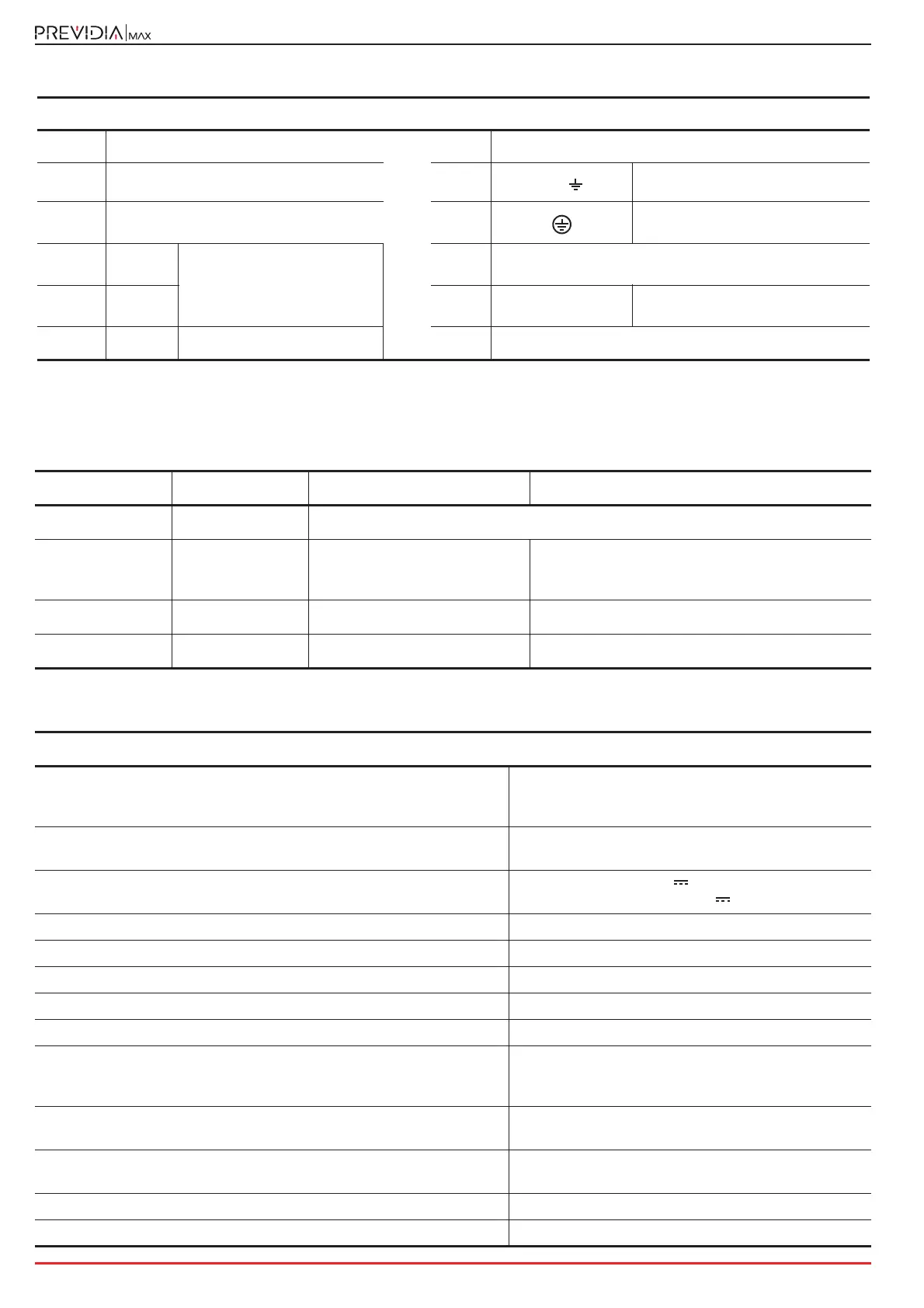
The indications in brackets below terminals OUT1, OUT2 and RELAY [D, E, F] show the respective factory default settings.
Figure 2 - IFM24160
[A]
Status LED
[G]
Battery connector
[B]
Mini USB port
[H]
L N
AC Mains input terminals
[C]
Jumper connectors for enablement of the
ground-fault test
[I]
Hole for the grounding bar screw
and for the earth conductor
[D] OUT1
Supervised output
[J]
Hole for the grounding bar screw and for the wire with the
eyelet terminal
[E] OUT 2 [K]
Input voltage
selector
230/115 V
[F] RELAY
Relay - voltage free contact
[L]
CAN drive connector (opposite)
IFM24160 LED Colour On solid Flashing
CAN
Blue Activity on the CAN communication BUS
ON
Green Module operating normally
Slow flashing: overload (system voltage draw is
excessive)
Fast flashing: PSU unit overheated
MAINS
Yellow Mains failure fault Fast flashing: system ground fault
BATT
Yellow Battery inefficiency or fault
IFM24160 module - technical specifications
Power supply voltage
230V~ (+10% - 15%)
115V~ (+10% - 15%)
50/60 Hz
Maximum current draw from mains
1.1A @ 230V
2A @ 115V
Output voltage
27.6 V nominal
20 - 27.6 V
Maximum output ripple 1%
Maximum available current 5.2A
Imax a (as per EN54-4) 4A
Imax b (as per EN54-4) 4A
Imin 185mA
Batteries
2 x 12 V 24Ah, NPL24-12I or
2 x 12 V 17 Ah, NP 17 -12-FR or equivalent
with UL94-V1 flame class enclosure or higher
Battery charger
Maximum voltage charge adapted to temperature
1.2A
Maximum internal resistance of battery
(Ri Max)
1Ohm
Battery shutdown voltage 19.5V
Operating temperature from -5°C to +40°C