Installation manual
Installation 31
English
4.4 IFM2L internal module wiring - loop connection
Refer to Figure 13 - Loop.
The connection circuits of the peripheral detection/activation devices are defined as “loops”. These loops start from the
output terminals, run through the entire protected area connecting in parallel all the system devices before re-entering
on the input terminals.
The loop utilizes the same two wires for the power supply to devices and for two-way communication. Due to electrical
incompatibility, different brand devices (i.e. devices using different protocols) cannot co-exist on the same loop.
However, the loops can be programmed separately in such a way as to allow the system to manage different brand
devices on different loops.
Loops are made by means of a two-wire shielded cable with proper wire section (refer to the following cable
specifications) and in compliance with local laws in force.
The wiring must be completed in a loop in order to guarantee the tolerance of wire-cutting or short-circuit on the cable.
Cables:
2 wire shielded cable
Twisted 5/10cm
Total maximum capacity 0.5uF
Maximum length 2000m
Maximum resistance (considering the sum of the positive
and negative conductor) 40Ohm
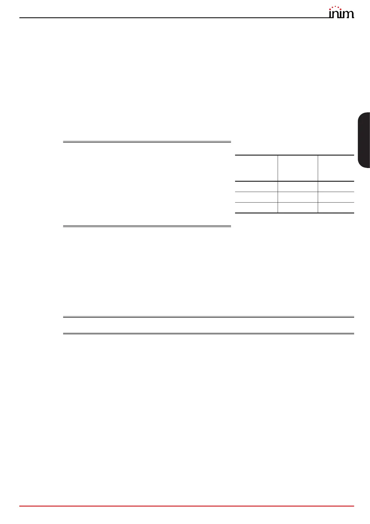
It is necessary to consult the configuration software,
Previdia/STUDIO, for the proper cable sizing in relation to
the power consumption of the connected devices, or to
the following table for a rough estimate:
The cable shield must be connected to the grounding bar at one end only.
For the connections of the various devices refer to the instructions supplied with the devices themselves.
The following diagram illustrates the proper completion of the loop wiring. Starting from Loop-A/B OUT terminals on the
IFM2L module ([A], paragraph 3.4 - [C] - [D]) proceed with the connection of the peripheral devices located in the area
protected by the system ([B]) and re-enter on Loop-A/B IN terminals ([C]).
When connecting the loop devices it is not necessary to follow the input/output order indicated in the figure. Connect
the cable shield only at the start of the loop ([D], the shield can be connected to the terminal indicated in the figure or
directly to the grounding bar). Take care to link the interrupted shields in correspondence with the device connections
([E]).
EN54:
A Previdia Max control panel can support up to 3840 fire detectors and/or manual call points (240
devices per loop).
4.5 System test
INIM Electronics recommends that the entire system be checked completely at regular intervals.
For the instructions for system testing and maintenance refer to the Manual for system configuration, commissioning
and maintenance.
Total loop
length
Wire
section
American
Wire
Gauge
Up to 1000m 2 x 1 mm² 17 AWG
Up to 1500m 2 x 1.5 mm² 16 AWG
Up to 2000m 2 x 2 mm² 14 AWG