6
SERIAL COMMUNICATION PROTOCOL
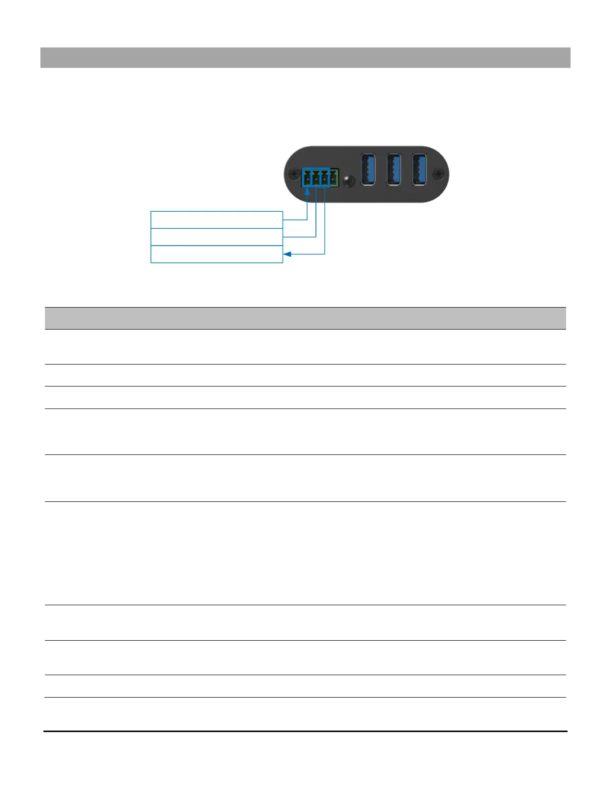
Here is the complete list of commands provided through the serial connection. Pinout is indicated on the enclosure.
GPI
RX
TX
GND
Connect to controller TX pin
Connect to controller RX pin
Connect to controller GND pin
Baud rate: 9600 // Data bits: 8 // Stop bits: 1 // Parity: None // Flow control: None
“FW_VER:X.Y”
where X = MAJOR and
Y = MINOR version.
Select PC.
0=OFF
1=PC1
2=PC2
Get PC selected.
0=OFF
1=PC1
2=PC2
“HOST_OFF“
“HOST_CHG“
“BTN“
“CMD“
Get last PC switching cause:
- HOST_OFF: No inputs selected. PC selection process
is changing between PC1 and PC2 or both hosts are
OFF.
HOST_CHG: PC1 or PC2 appeared / disappeared in
mode AUTO;
- BTN: Button has been used to change PC selection.
- CMD: RS232 command has been used to change PC
selection.
“X.YZV“
Where X = units value
YZ = decimal value
“X.YZA“
Where X = units value
YZ = decimal value
Set GPIN mode: (pulse =’0’, level = ‘1’)