3 9
CPS 220/64/SV Montage- und Betriebsanleitung
CPS 220/64/SV Mounting and Operating Instructions
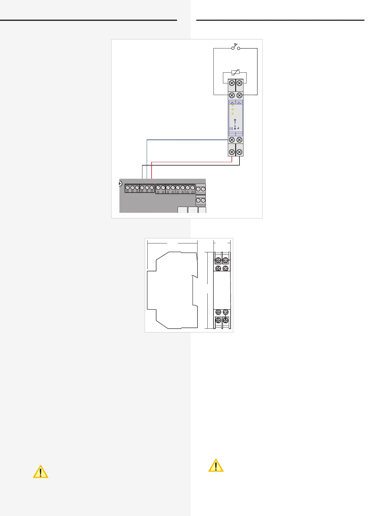
6.3.4.6. Central dimming
The optional CLS dimmer module
allows programmed luminaires
in the circuits to be dimmed cen-
trally via
• Buttons on the CLS dimmer
module
• An externally connected button
• A 0–10 V control voltage
This can be done variably in 10%
increments from 0% (luminaire
off) up to 100% (luminaire on).
Accordingly, the emergency light-
ing luminaires are to be dimmed
together with the general lighting
luminaires (e.g. via an EIB module).
In emergency operation, the lumi-
naires switch to 100% automati-
cally.
Technical data:
Amb. temp. range: -15°C to +40°C
Housing: Thermoplast V0
Conductor
connection:
2.5 mm² single-wire
or 1.5 mm² cord with
cable end sleeve
EMC protection: as per DIN EN 55015
Protection class: I
Protection
category:
IP20
EMC protection: as per DIN EN 55015
6.3.5. Additional components
Additional components enhance the functionality of the
CPS 220/64 – system.
6.3.5.1. RIF 5
The RIF 5 is fitted into devices CPS 220/64 and CPUS
220/20 at delivery. The assembly provides volt-free sig-
nalling contacts and connections for the remote switch-
ing circuit and the current loops and also monitors the
main distribution board and the battery voltage.
A maximum of one active RIF 5 can be connected
to each CPS controller. However, the signalling
contacts can be reproduced manifold using pas-
sive RIF 5 modules. This requires the module address "0"
to be set and the monitoring loop function (SLÜ) to be
6.3.4.6. Zentrales Dimmen
Mit dem optionalen CLS-
Dimmer Modul können ent-
sprechend programmierte
Leuchten in den Stromkrei-
sen über
• Taster am CLS Dimmer
Modul
• einen extern
angeschlossenen Taster
• eine 0-10V Steuerspannung
zentral gedimmt werden,
regelbar in 10%-Stufen von
0% (Leuchte aus) bis zu 100%
(Leuchte ein).
Damit sind die Leuchten der
Notbeleuchtung mit denen
der Allgemeinbeleuchtung
gemeinsam zu dimmen (z.B.
über ein EIB-Modul). Im Not-
betrieb schalten die Leuchten
automatisch auf 100%.
Technische Daten:
Temp.-Bereich: -15°C ... +40°C
Gehäuse: Thermoplast V0
Leiteranschluss: 2,5mm² eindrähtig
oder 1,5mm² Litze mit
Aderendhülse
Funkentstörung: gem. DIN EN 55015
Schutzklasse: I
Schutzart: IP20
Funkentstörung: gem. DIN EN 55015
6.3.5. Zusätzliche Komponenten
Zusätzliche Komponenten erweitern die Funktionalität
des CPS 220 / 64 – Systems.
6.3.5.1. RIF 5
Das RIF 5 ist werksseitig in die Geräte CPS 220/64 und
CPUS 220/20 eingebaut. Die Baugruppe stellt neben
potentialfreien Meldekontakten noch Anschlüsse für
den Fernschaltkreis und die Stromschleife zur Verfügung,
sowie dient sie zur Überwachung des Hauptverteilers und
der Batteriespannung.
An jedes CPS-Steuerteil kann max. ein aktives RIF 5
angeschlossen werden. Durch passive RIF 5 -
Module lassen sich jedoch die Meldekontakte ver-
vielfältigen. Dazu ist die Moduladresse „0“ einzustellen
R T G IBa IBp IBp
+24V
T
FSSL
+– +–
+24V
+–
Opt.
Stoer
Potenziometer
0-10V
oder
0 - 10V
Taster
Taster ext.
+24V
Bus
CLS-DimmerINOTEC
850 013
T
T
EMC : gem. EN 55015
Ta : -15 bis 40°C
+ 0-10V - 0-10V
59
90
17,5
 Loading...