Inovance H0U Series PLC User Manual
Page 6 of 14
Electrical Design
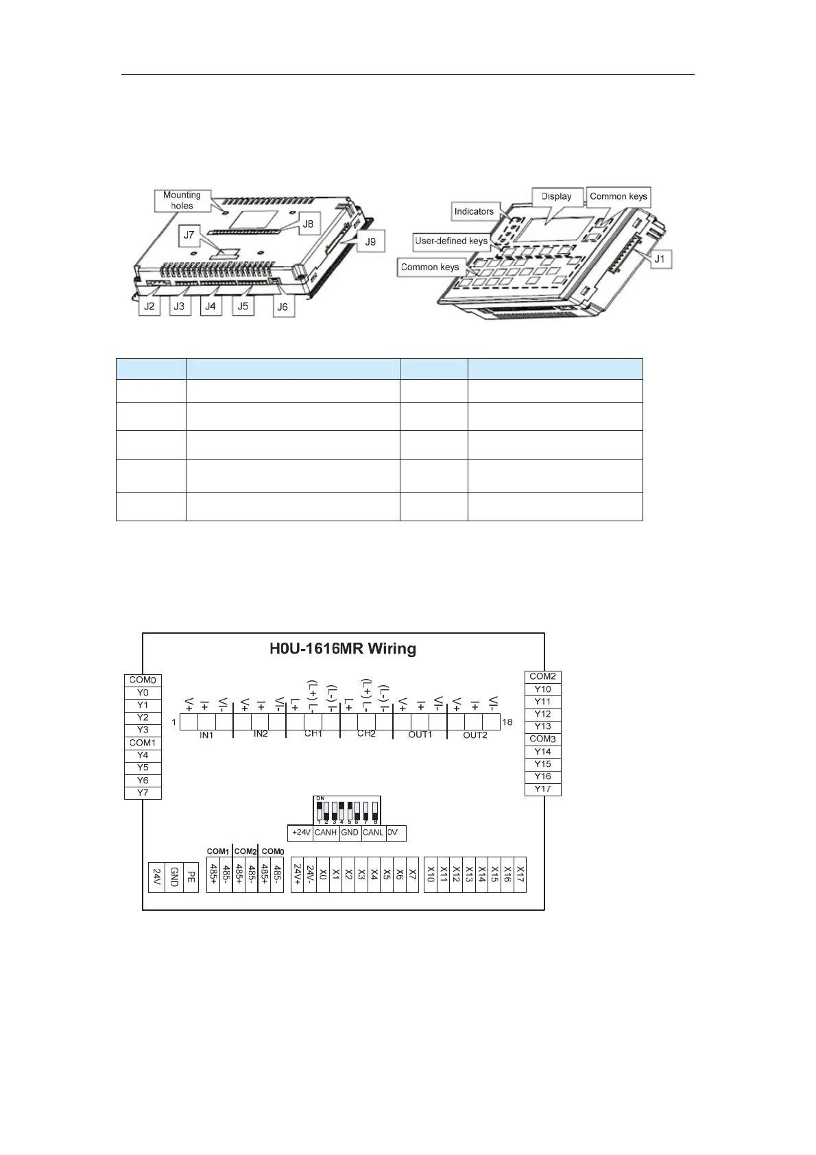
The following figure shows the structure of the H0U series PLC.
Table 3 Structure of the H0U series PLC
Terminal Terminal Name Terminal Terminal Name
J1 Output terminals (Y0 to Y7) J2 Power supply interface
J3 Serial communication port (RS485) J4 Input terminals (X0 to X7)
J5 Input terminals (X10 to X17) J6 USB client (Type B)
J7 Used for extended CAN function J8
Interface for built-in analog
extension card
J9 Output terminals (Y10 to Y17)
Wiring (Hardware)
The following figure shows the wiring of the H0U series PLC.
Figure 2 Wiring of the H0U series PLC
Communication Ports
The H0U series PLC has four communication ports as standard configuration. COM0,
COM1 and COM2 are standard RS485 communication interfaces. COM0 is used for user
program downloading, commissioning and monitoring. COM1 and COM2 are free
interfaces and support the Modbus protocol, N:N protocol, parallel protocol, HMI protocol,
efesotomas
on.com

 Loading...


