- 7 -
2 Installation
2. Installation
2.1 Installation Environment
Ambient temperature: The HMI works stably in the temperature range of 0°C to 50°C
(32°F~122°F). Using the HMI outside the temperature range may cause damage
to HMI components, abnormal operation or performance deterioration. If the HMI
needs to be used in specic occasions outdoors, contact your supplier.
Install the HMI free from strong mechanical vibration.
Install the HMI in the panel of over 105 mm depth. Ensure at least 25 mm clearances
surrounding the HMI.
When connecting other devices to the HMI, make sure to locate the AC power cable,
output module, contactor, AC drive, relay, and electrical devices of other types away
from the back of the HMI. Use shielded cables as input and output cables of the
equipment and properly ground the shielded cables.
The front panel of the HMI meets the IP65 protection regulations. When the HMI is
properly installed into the cabinet complying with IP65 protection regulations, the
cabinet still meets the IP65 protection regulations. That is, when liquid is sprayed on
the surface of the cabinet, the liquid will not go inside the cabinet.
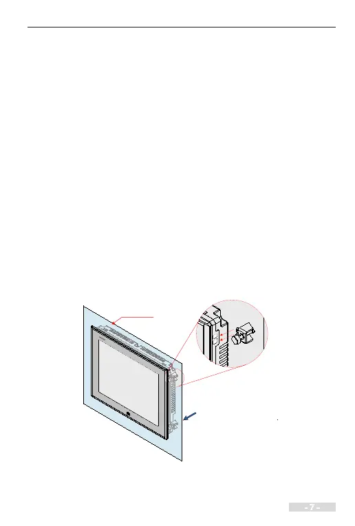
2.2 Mounting Method
Metal panel
② Tighten the clamp screws
.
①
Put the clamp screws
into the clamp holes around
the housing of the HMI.
Through-Hole Mounting
Note: Only IT6100E HMI supports VESA mounting. Install the HMI by using the 4 x
M4 VESA mounting holes at the back side.