Adjustment Instructions
1 Safety Instructions
1.1 Power supply must be cut off when replacing or welding any component or inserting / pulling out
connective lines;
1.2 Anti-electrostatic measures must be carried out during the whole producing processes!
a) Do not touch IC by hands at will;
b) Use anti-electrostatic iron;
c) Welder must wear anti-electrostatic glove;
1.3 Replacing any component with special safety requirement must refer to component list without
changing its specification and model at will.
1.4 Power supply voltage must be 120 V±10%, or 220 V would burn out power board.
2 Adjustment Equipments
VG-848 (YPbPr, VGA signal generator)
DVD (HDMI signal generator)
CA-210
3 Adjustment Processes
3.1 Power voltage test
According to the wiring diagram ‘92XXMF7001JL’ or ‘92XXMF7501JL’, connect power board
assembly, data processing assembly, IR/Key board assembly, backlight board assembly correctly,
supply with power, press button standby to power on the TV set.
3.1.1 Model LC-37/39/42/46MFXX
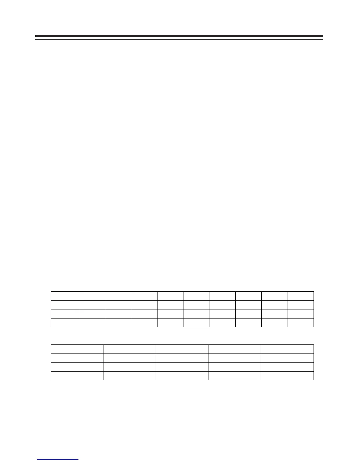
a) Test voltage of X504 each pin on power board in turn shown as Table 1:
Table 1 Voltage of X504 each pin
X504
Pin 1、2 3、4 5、6 7、8
9 10 11 12 13
Min. (V) 11.3 0 11.3 0 2.85 4.85 4.85 3.25 4.85
Typical(V) 12.0 0 12.0 0 3.00 5.00 5.00 3.30 5.00
Max. (V) 12.6 0 12.6 0 3.15 5.35 5.35 3.30 5.35
b) Test voltage of X505 each pin on power board in turn shown as Table 2:
Table 2 Voltage of X505 each pin
X505 Pin 1 2
3~7 8~12
Min. (V) 3.25 4.85 0 23.8
Typical(V) 3.30 5.0 0 24.0
Max. (V) 3.30 5.35 0 25.2
Aligment Instructions
 Loading...