Do you have a question about the insize ISR-C300 and is the answer not in the manual?
Details the composite structure, connectivity, multi-parameters, LCD display, DSP chip, standards compliance, battery, data storage, and software features.
Explains how the pickup traces the surface, converts displacement to an analog signal, and is processed by the DSP chip for measurement results.
Lists the standard items included with the instrument, such as probes, cables, and adapters.
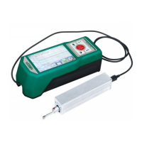
Identifies the main display unit, drive unit, and associated components like the fix board and pin shaft.
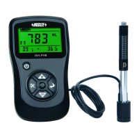
Details the layout of the front panel of the Master Display Unit, including buttons and indicators.
Explains the operation of the Power key for on/off and the Start key for initiating measurements.
Describes the function of Up, Down, Cancel/Exit, and Enter keys for menu navigation and parameter adjustment.
Details the purpose of specific touch-sensitive areas on the display for functions like zooming and viewing results.
Details the procedure and requirements for charging the instrument's lithium-ion battery via USB or adapter.
Provides instructions on how to connect and disconnect the sensor and drive unit, emphasizing care for the stylus.
Explains the installation process for connecting the drive unit to the main display unit using fixed pin shafts.
Covers pre-measurement checks, surface preparation, and powering the instrument on and off.
Explains how to correctly position the pickup on the surface to ensure accurate roughness measurements.
Details the step-by-step procedure for detaching the drive unit from the main display unit.
Explains how to use the extension cable to connect the main display unit and drive unit when they are not directly attached.
Instructs on how to initiate a measurement by pressing the Start key or its touch area.
Explains how to view all measurement results and use the profile display area for zooming.
Details how to print measurement data to a serial printer and configure print output.
Explains how to save measurement results to the instrument's internal memory.
Guides on accessing the main menu to configure various instrument settings.
Covers settings like Ra, Rmax, BPS rate, Bluetooth mode, Auto Shutdown, and Print.
Includes settings for Touch Screen Calibration, RPC Details, Date & Time, TFT Brightness, Reset, and Format Memory.
Allows user-defined selection of Rpc-parameter calculation between 'µm' and '%'.
Provides instructions on how to adjust the instrument's date and time settings.
Explains how to adjust the brightness of the LCD display.
Guides on how to restore the instrument to its original factory default settings.
Details the process of data formatting, which erases all stored data records.
Explains how to set measurement conditions such as cutoff length, range, unit, and filter.
Describes how to manage and view stored measurement records.
Provides access to instrument software and hardware details for upgrade and maintenance.
Guides on calibrating the instrument using a standard calibration block for improved accuracy.
Explains how to configure print settings for parameters or all data.
Explains how to output measurement data to Excel via Bluetooth connection.
Details how to use the mobile APP for remote control and data transmission via Bluetooth.
Describes using Dataview software for waveform analysis and uploading measurement results to a PC.
Explains the use of adjustable support feet for stabilizing measurements on smaller workpieces.
Details the use of a height gauge adapter for specific measurement setups.
Explains the use of a 50mm extension rod to increase the pickup's reach depth.
Provides dimensions and details for the standard groove sensor.
Explains the measurement capabilities and mounting requirements for the small hole sensor.
Details the operation and mounting of the extra small hole sensor for specific hole measurements.
Describes the use of the deep groove sensor for measuring deep grooves and shallow steps.
Explains the use of a support for measuring objects smaller than the tester on a flat plane.
Explains how to measure cylindrical objects where direct measurement is not feasible.
Details the connection process and settings for using a Bluetooth printer with the roughness meter.
Lists the vertical and horizontal measurement ranges and resolution of the instrument.
Details the available evaluation parameters and the international standards the instrument complies with.
Specifies details about the sensor, stylus, measuring force, and measurement principle.
Provides specifications for accuracy, repeatability, battery, and working time.
Lists the dimensions of display and drive units, mass, and working/storage environment conditions.
Details the specific measuring ranges for various roughness parameters like Ra, Rz, Rq, etc.
Provides essential advice for handling the probe carefully to avoid damage and ensure longevity.
Advises on maintaining the cleanliness of the main unit's surface with a soft dry cloth.
Reminds users to observe battery prompts and charge when low, suggesting a 3-hour charging time.
Emphasizes keeping the standard sample plate surface clean and avoiding scratches.
Guides on handling common faults like display issues, motor errors, and touchscreen failures.
Defines key terms related to filter profiles, direct profiles, and surface texture parameters.
Explains traversing length concepts for RC, PC-RC, and GAUSS filters.
Defines Ra as the arithmetic mean of absolute profile deviations within the sampling length.
Defines Rq as the root of the mean square of profile deviations within the sampling length.
Defines Rz as the sum of the highest peak and deepest valley from the mean line within the sampling length.
Defines Rt as the sum of the highest peak and deepest valley over the evaluation length.
Provides a table correlating Ra, Rz values with recommended sampling lengths.
| Brand | insize |
|---|---|
| Model | ISR-C300 |
| Category | Test Equipment |
| Language | English |