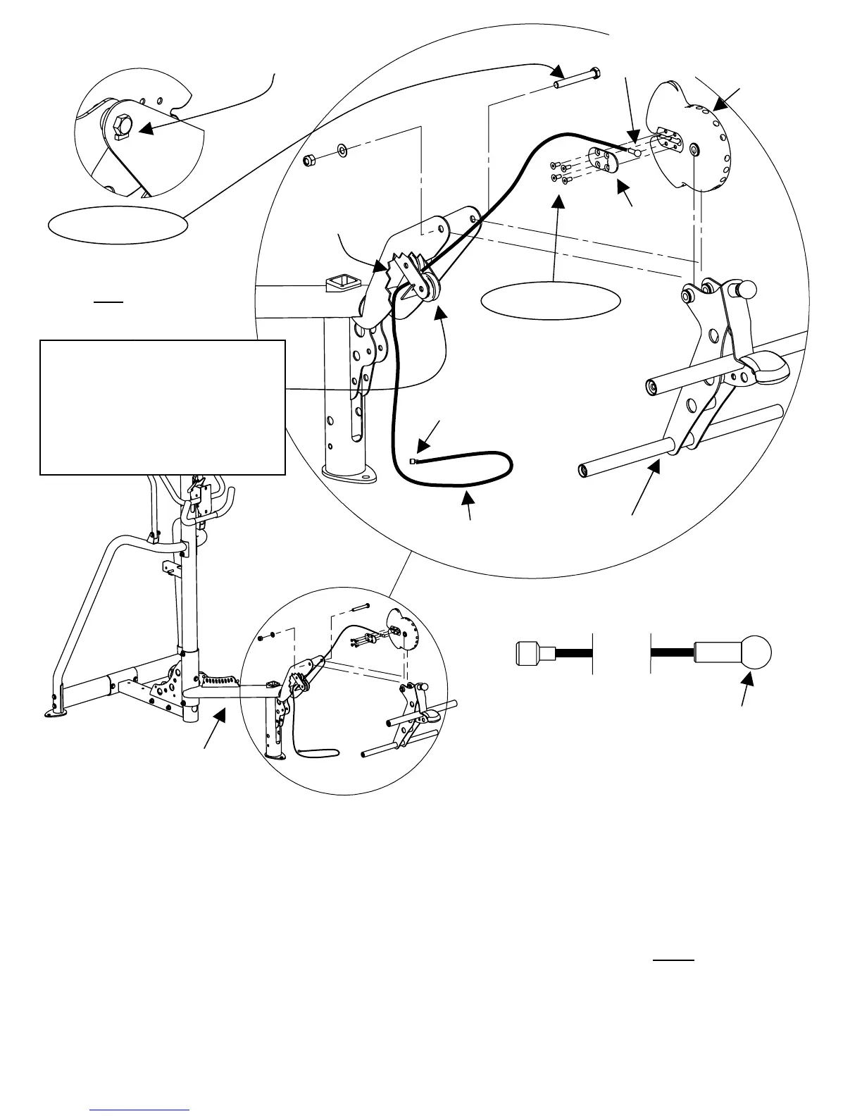
Large Ball
L/E Cam
Bolt Head must fit snug against Anti-Rotation Tab
Pre-assembled Cam Plate
Pulleys
1 – ½” x 3 ¾” Hex Bolt
1 – ½” Flat Washers
1 – ½” Thin Lock Nut
Note: washer on nut side only.
4 – ¼” Flat Head Cap Screws
1 – Cam Plate
Small Cable End
Leg Extension Cable L/E Assembly
Seat Base Frame
Step 15: Begin by removing the 4 Flat Head Cap Screws and the Cam Plate from the Leg
Extension Cam (L/E Cam). Next, using these same 4 Flat Head Cap Screws and the
Cam Plate, attach the Leg Extension cable to the L/E Cam, as shown in the above
diagram.
Step 16: Attach L/E Cam and L/E Assembly to Seat Base One (1/2” x 3 ¾” Hex Bolt)
Frame using: One (1/2” Flat Washers)
One (1/2”
Thin Lock Nut)
NOTE: Washer on nut side only.
NOTE: Be sure to thread Leg Extension Cable through pre-assembled pulleys as L/E Cam and
L/E Assembly are attached.
NOTE: Wrench Tighten Now, Do Not Over Tighten. L/E Assembly should move freely.
Page 16
STEP 15
STEP 16
This large Ball End to be attached to
L/E Cam as shown above.
NOTE: If small cable end won’t fit
between pre-assembled Pulleys,
loosen or remove Lower Pulley,
insert cable end between the Upper
Pulley and the metal plate, then re-
attach the Lower Pulley.