DTA-9.4
OUTPUT
Fig-1
CENTER
LEFT
RIGHT
OUTPUT
Fig-2
CENTER
LEFT
RIGHT
OUTPUT
Fig-3
CENTER
LEFT
RIGHT
OPERATION CHECK-6
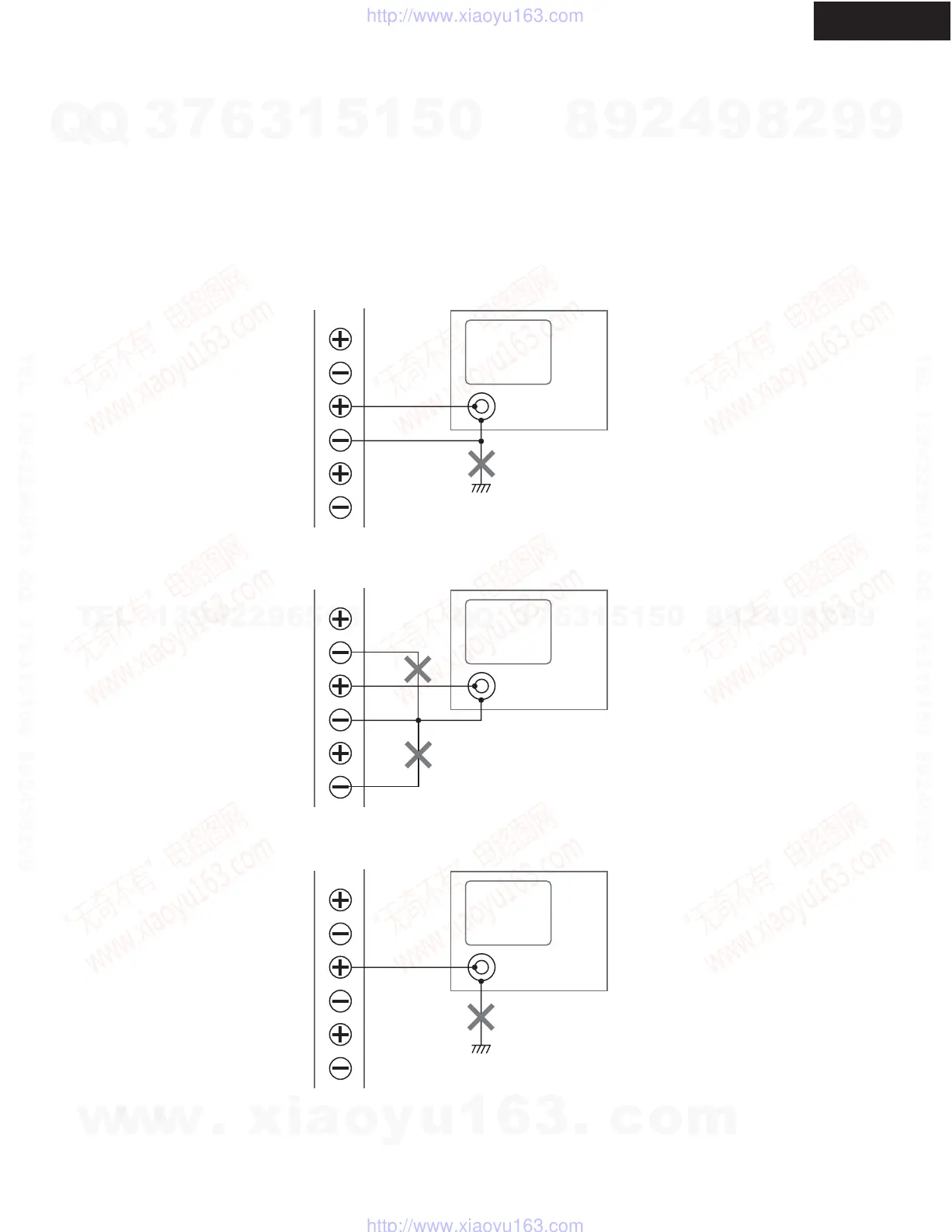
CAUTION IN THE CASE OF SPEAKER OUTPUT CHECK
The power amplifier circuit of DTA-9.4 is BTL system.
Therefore, in case you check speaker output, should be careful of the following point.
1. Do not connect the minus side OUTPUT terminal, and ground of the unit (Fig-1).
2. Do not connect minus of each OUTPUT terminal. (Fig-2).
3. Cannot check with an oscilloscope between the plus side of an OUTPUT terminal, and Chassis GND. (Fig-3).
Oscilloscope
Chassis GND of unit
Chassis GND of unit
w
w
w
.
x
i
a
o
y
u
1
6
3
.
c
o
m
Q
Q
3
7
6
3
1
5
1
5
0
9
9
2
8
9
4
2
9
8
T
E
L
1
3
9
4
2
2
9
6
5
1
3
9
9
2
8
9
4
2
9
8
0
5
1
5
1
3
6
7
3
Q
Q
TEL 13942296513 QQ 376315150 892498299
TEL 13942296513 QQ 376315150 892498299
http://www.xiaoyu163.com
http://www.xiaoyu163.com
 Loading...