DTA-9.4
U5
NAPS-7790
R861
Q801
E881
E806
P801C
P801C
Q812
Q813
Q817
Q814
T853
P902B
P803A
T851
T854
T852
PRI
SEC
Q842
E891
E893
E894
E892
E895
Q851
D851
R181
Q881
Q882
Q883
Q884
R848
JL805B
E841
AC-H2 AC-G2
TH1 PROT
+B
CTRL1
+B
CTRL2
GND2
TH1
TH2-
TH2+
U1
NAPS-7788
NAPS-7789
D136
E113
E112
R139
D133
D161
P903B
P131A
D920D921 D922
D923
E101
JL9906B
Q103
E114
P101A
P108
E126 E125
E122 E121
E124 E123
JL132B
L101
L102
E102
E192
E191
P161
RL+
GND2
RL-
RL+
RL-
+12V
PROT
+12V
GND2
PROT
TEST
VOLTAGE
ADJUST
VOLTAGE
CHECK
REGULATED
LOW
CURRENT
TH1
GND2
TH2+
TH2-
CTRL1
CTRL2
+B
+B
+B
GND
-B
PROT
+B
E
-B
E173
E174
E175
L906
P904
P903A
P902A
D902
RL901
RL902
RL902
T902
T901
AC-H
AC-G
UDD
UDD
UDD UJJ
UJJ
UJJ
D102 D101D104 D103
UDD
UJJ
E985B
E990
E988
E991
E989
E986
E982
E984
E981
P996B
P801B
P801A
E987
E983
E985A
PRI
SEC
SEC
PRI
WHT
BLK
WHT
BLK
P101B
L103
D907
E904
E902
E901
E903
E905
E906
GND
AC-G2
AC-H2
GND2
RL+
RL-
+-
12V INPUT
FOR TEST
VC+
VC-
VC-
LIVE
PRI DC
P997B
TH1 PRO
D851
(RED)
PRI DC
LIVE
D907
(RED)
PROT
D161
(RED)
LOW
CURRENT
D136
(RED)
REGULATED
D133
(RED)
U2
OPERATION CHECK-5
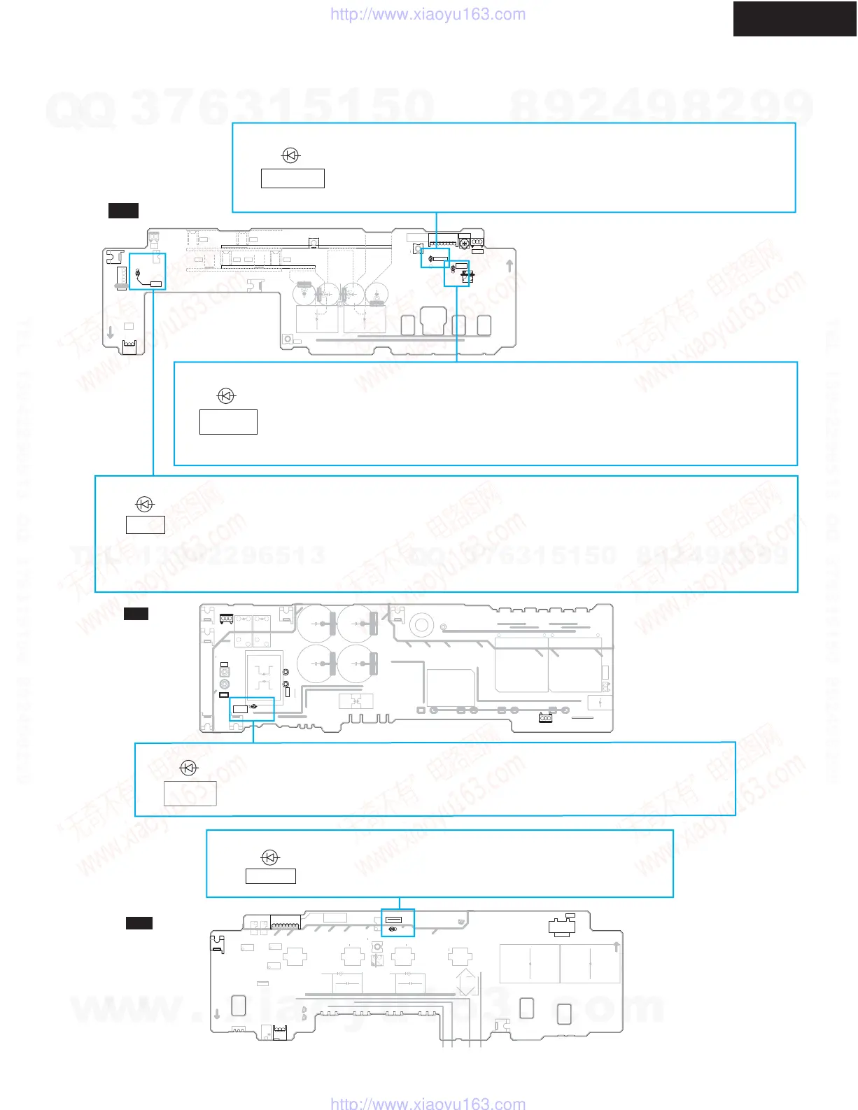
OPERATION INDICATOR IN THE UNIT-2
D133 (REGULATED)
This LED is turned on when the voltage of a secondary power supply output is normal.
The detection circuit which is source of the drive about this LED is supervising only
the voltage difference between the positive power supply of secondary voltage, and the
negative power supply.
D136 (LOW CURRENT)
This LED is turned on when a low load measure circuit operates.
When the switching power supply of this unit has very little load to a power supply,
the voltage of a secondary side output rises rapidly.
In such a case, a problem is avoided by lowering voltage.
This circuit may operate temporarily at the time of a power supply ON.
D161 (PROT)
This LED is turned on when the protection circuit of a power supply operates.
The protection circuit of a power supply section consists of following detection circuits.
1. Over voltage detection of a secondary DC output.
2. Thermal detection of primary power supply circuit.
3. Thermal detection of secondary power supply circuit.
This LED may be turned on only for a moment. It is because the state of a protection circuit is not held in NAPS-7789.
D907 (PRI DC LIVE)
This LED is turned on when the electric charge remains in the primary side capacitor.
Do after discharging by resistance and checking putting out lights of this LED, when
disassembling a unit.
D851 (TH1 PROT)
This LED lights up at the time of the usual operation.
The light is put out when the thermal protection circuit of
a primary power supply section operates.
w
w
w
.
x
i
a
o
y
u
1
6
3
.
c
o
m
Q
Q
3
7
6
3
1
5
1
5
0
9
9
2
8
9
4
2
9
8
T
E
L
1
3
9
4
2
2
9
6
5
1
3
9
9
2
8
9
4
2
9
8
0
5
1
5
1
3
6
7
3
Q
Q
TEL 13942296513 QQ 376315150 892498299
TEL 13942296513 QQ 376315150 892498299
http://www.xiaoyu163.com
http://www.xiaoyu163.com
 Loading...