EasyManua.ls Logo

Integra ADM-2.1 - User Manual

Integra ADM-2.1
8 pages
Print Icon
To Next Page IconTo Next Page
Loading...
Contents
Thank you for purchasing the Integra 2 Channel
Amplifier.
Please read this manual thoroughly before making
connections and plugging in the unit.
Following the instructions in this manual will enable
you to obtain optimum performance and listening
enjoyment from your new 2 Channel Amplifier. Please
retain this manual for future reference.
ADM-2.1
2 Channel Amplifier
Instruction Manual
Before using
Important Safeguards ....................................... 2
Features............................................................. 3
Supplied accessory ........................................... 3
Precautions........................................................ 3
Facilities and connections
Rear panel facilities and connections ............... 4
Connection diagram.......................................... 5
Front panel facilities and connections.............. 6
Operations......................................................... 7
Appendix
Troubleshooting guide...................................... 7
Specifications ...................................Back cover
#US_ADM-2.1_01.p65 8/25/00, 6:22 PM1
Question and Answer IconNeed help?

Do you have a question about the Integra ADM-2.1 and is the answer not in the manual?

Integra ADM-2.1 Specifications

Amplifier Section IconAmplifier Section
power output at 8 ohms100 Watts per channel
power output at 6 ohms125 Watts per channel
dynamic power output at 8 ohms2 × 140 Watts
total harmonic distortion at rated power0.08 %
IM distortion at rated power0.08 %
damping factor at 8 ohms100
input sensitivity and impedance1 V, 50 kohms
output level and impedance1 V, 10 kohms
rated speaker impedance6 ohms MIN
frequency response10 Hz – 100 kHz, ±1 dB
signal-to-noise ratio110 dB (IHF A, 0.5 V input)
General IconGeneral
power supplyAC 120 V, 60 Hz
power consumption2.5 A
dimensions (W × H × D)435 × 145 × 316 mm
weight8.5 kg

Summary

Important Safeguards

Features

Precautions

Supplied Accessory

Rear Panel Facilities and Connections

GND Terminal

Ground terminal for connecting earth wire to prevent humming noise.

Audio Input;Output Jacks

Analog audio inputs/outputs for connecting source devices or linking units.

Input Level Adjustment

Control to adjust signal input level from AUDIO IN jacks.

Trigger Switch

Controls automatic power on/off via signal input or 12V trigger.

12 V Trigger In Jack

Input for 12V DC signal to control standby/on states remotely.

Speaker Terminals

Terminals for connecting speakers, compatible with banana plugs.

AC Inlet

Connection point for the supplied power cord.

Connection Diagram

Front Panel Facilities and Connections

Power Button Operation

Explains operation of the power button based on trigger switch settings.

Standby;On Indicator

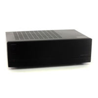
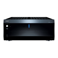
Describes the color and meaning of the unit's status indicator light.

Operations

Troubleshooting Guide

Specifications

Related product manuals