DTM-5.9
ADJUSTMENT PROCEDURE
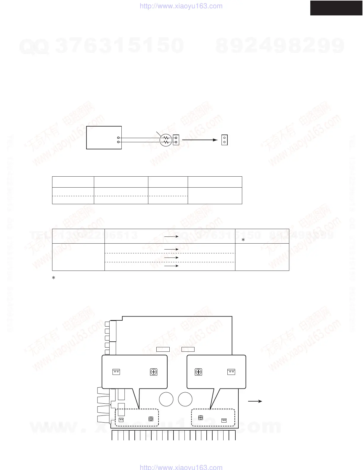
IDLING CURRENT ADJUSTMENT
Adjustment points Adjustment valueTest points
4.5 mV
Leave it as it is
5.5 mV
In case below 4.4 mV
In case 4.5 - 5.5 mV
In case over 5.6 mV
Channel
Left and Right
ID+
ID-
Test point
DC voltmeter
Jig terminal
100 ohms
(1/4 watt)
6 +/- 2 mV
Idling currents are stabilized in about 10 minutes after power on.
[When]
1. Exchange Power transistor (Q521 - Q524).
2. Exchange Amplifier PC board (NAAF-9610).
[Procedure]
<Note> No load and No signal
Refer to <Fig-1> for the adjustment points and the test points.
1. Before idling adjustment, turn the trimming resistors fully to counter clockwise.
2. Connect the dc voltmeter to test points, using two 100 ohm resistors between the poles of the jig terminal and
the DC voltmeter terminals.
3. Connect the AC power cord to a wall outlet.
4. Press On/Standby button to turn the power on.
5. Adjust the trimming resistors as the following procedure immediately after power on.
6. Wait for 4 - 6 minutes. (Heat running)
7. Re-adjust the trimming resistors as the following procedure.
8. Disconnect the DC voltmeter.
9. Press On/Standby button to turn the power off.
10. Disconnect the AC power cord.
Channel Measured value Adjustment value
Spec.
( In a stable state)
<Fig-1>
Amplifier PC board
(NAAF-9610)
Front side
LEFTRIGHT
2.5 mV
Left
Right
R587
R588
P511
P512
R587R588 P511P512
ID+
ID-
ID+
ID-
Left ch
Right ch
w
w
w
.
x
i
a
o
y
u
1
6
3
.
c
o
m
Q
Q
3
7
6
3
1
5
1
5
0
9
9
2
8
9
4
2
9
8
T
E
L
1
3
9
4
2
2
9
6
5
1
3
9
9
2
8
9
4
2
9
8
0
5
1
5
1
3
6
7
3
Q
Q
TEL 13942296513 QQ 376315150 892498299
TEL 13942296513 QQ 376315150 892498299
http://www.xiaoyu163.com
http://www.xiaoyu163.com
 Loading...