OVERVIEW OF NUMERIC PROCESSING
TAG
VALUES:
00
VALID
01
ZERO
10
INVALID
OR
INFINITY
11
EMPTY
Figure 1-6.
80287
Tag Word Format
15
CONTROL WORD
STATUS WORD
TAG
WORD
INSTRUCTION POINTER (15-0)
INSTRUCTION
;)1
'I
INSTRUCTION
POINTER (19-16) 0
OPCODE (10-0)
DATA POINTER (15-01
DATA POINTER
1
(19-16)
0
15
1211
REAL
MODE
MEMORY
OFFSET
to
+4
+6
+8·
+10
+12
15
CONTROL WORD
'.
STATUS WORD
TAG
WORD
IPOFFSET
CSSELECTOR
DATA
OPERAND OFFSET
DATA OPERAND SELECTOR
PROTECTED
MODE
G30108
MEMORY OFFSET
+0
+2
+4
+6
+8
+10
+12
G30108
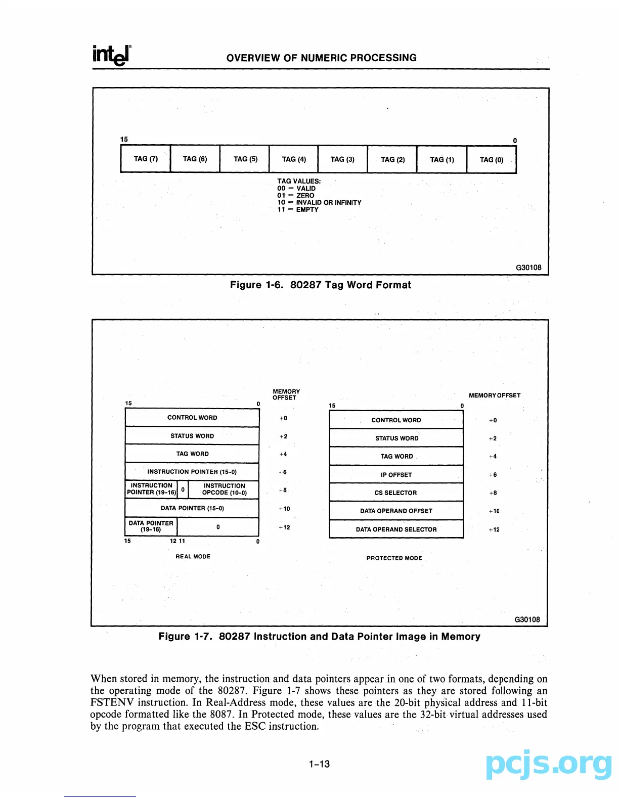
Figure 1-7.
80287
Instruction and Data POinter Image
in
Memory
When stored in memory, the instruction and data pointers appear in one of
two
formats, depending
on
the operating mode of the 80287. Figure
1-7
shows
these pointers
as
they are stored following an
FSTENV instruction. In Real-Address mode, these values are the 20-bit physical address and
ll-bit
opcode formatted like the 8087. In Protected mode, these values are the 32-bit virtual addresses used
by the program that executed the ESC instruction.
1-13