Installing and Replacing Desktop Board Components
49
Pin Standard Signal Name ECP Signal Name EPP Signal Name
24 GROUND GROUND GROUND
25 SELECT SELECT SELECT
26 KEY (no pin) KEY (no pin) KEY (no pin)
IEEE 1394a Header
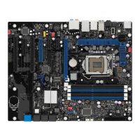
See Figure 22, E for the location of the IEEE 1394a header. Table 10 shows the pin
assignments for the header.
Table 10. IEEE 1394a Header Signal Names
Pin Signal Name Pin Signal Name
1 TPA1+ 2 TPA1-
3 Ground 4 Ground
5 TPA2+ 6 TPA2-
7 +12 V 8 +12 V
9 Key (no pin) 10 Ground
Front Panel Header
See Figure 22, F for the location of the front panel header. Table 11 shows the pin
assignments for the front panel header.
Table 11. Front Panel Header Signal Names
Pin Signal Name In/Out
Pin Signal Name In/Out
Hard Drive Activity LED Power LED
1 Hard disk LED pull-up to +5 V
Out 2 Front panel green LED Out
3 Hard disk active LED Out 4 Front panel yellow LED Out
Reset Switch On/Off Switch
5 Ground 6 Power switch In
7 Reset switch In 8 Ground
Power Not Connected
9 Power Out 10 No pin