Intel Desktop Board D201GLY2 Product Guide
16
LAN Subsystem Software
For LAN software and drivers, refer to the D201GLY2 link on Intel’s World Wide Web
site at:
http://support.intel.com/support/motherboards/desktop
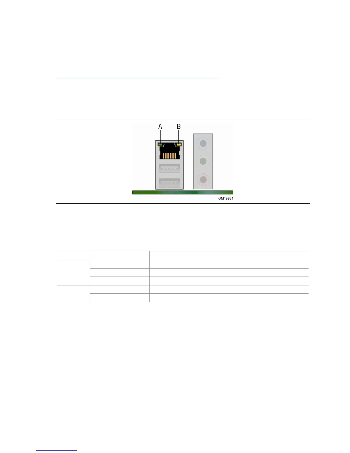
RJ-45 LAN Connector LEDs
Two LEDs are built into the RJ-45 LAN connector located on the back panel (see
Figure 3).
Figure 3. LAN Connector LEDs
Table 3 describes the LED states when the board is powered up and the
10/100 Ethernet LAN subsystem is operating.
Table 3. RJ-45 10/100 Ethernet LAN Connector LEDs
LED LED State Indicates
Off LAN link is not established A (Green)
On LAN link is established
Blinking LAN activity is occurring
Off 10 Mbits/s data rate is selected B (Yellow)
On (steady state) 100 Mbits/s data rate is selected
 Loading...