Intel Desktop Board DB65AL Product Guide
46
Serial Header
Figure 21, C shows the location of the serial header. Table 7 shows the pin
assignments and signal names for the serial header.
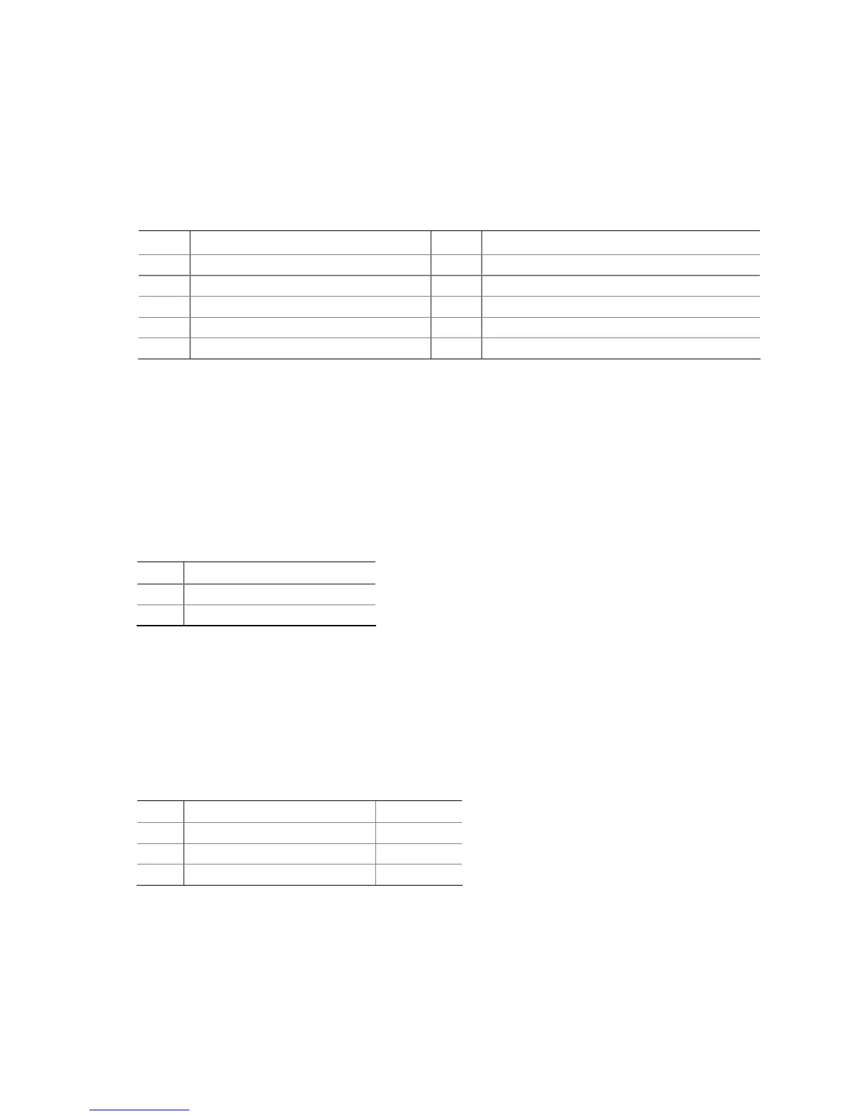
Table 7. Serial Port Header
Pin Signal Name Pin Signal Name
1 DCD (Data Carrier Detect) 2 RXD# (Receive Data)
3 TXD# (Transmit Data) 4 DTR (Data Terminal Ready)
5 Ground 6 DSR (Data Set Ready)
7 RTS (Request To Send) 8 CTS (Clear To Send)
9 RI (Ring Indicator) 10 Key (no pin)
Chassis Intrusion Header
Figure 21, D shows the location of the chassis intrusion header. This header can be
connected to a mechanical switch on the chassis to detect if the chassis cover is
removed. This switch should be in the open position when the chassis cover is
installed and closed when the cover is removed.
Table 8 shows the pin assignments and
signal names for the chassis intrusion header.
Table 8. Chassis Intrusion Header Signal Names
Pin Description
1 Intruder#
2 Ground
Alternate Front Panel Power LED Header
Figure 21, E shows the location of the alternate front panel power LED header. Pins 1
and 3 of this header duplicate the signals on pins 2 and 4 of the front panel header. If
your chassis has a three-pin power LED cable, connect it to this header. Table 9
shows
the pin assignments for the alternate front panel header.
Table 9. Alternate Front Panel Power LED Header Signal Names
Pin Signal Name In/Out
1 Front panel LED+ Out
2 No pin
3 Front panel LED- Out