Installing and Replacing Desktop Board Components
47
Front Panel Header
Figure 21, F shows the location of the front panel header. Table 10 shows the pin
assignments and signal names for the front panel header.
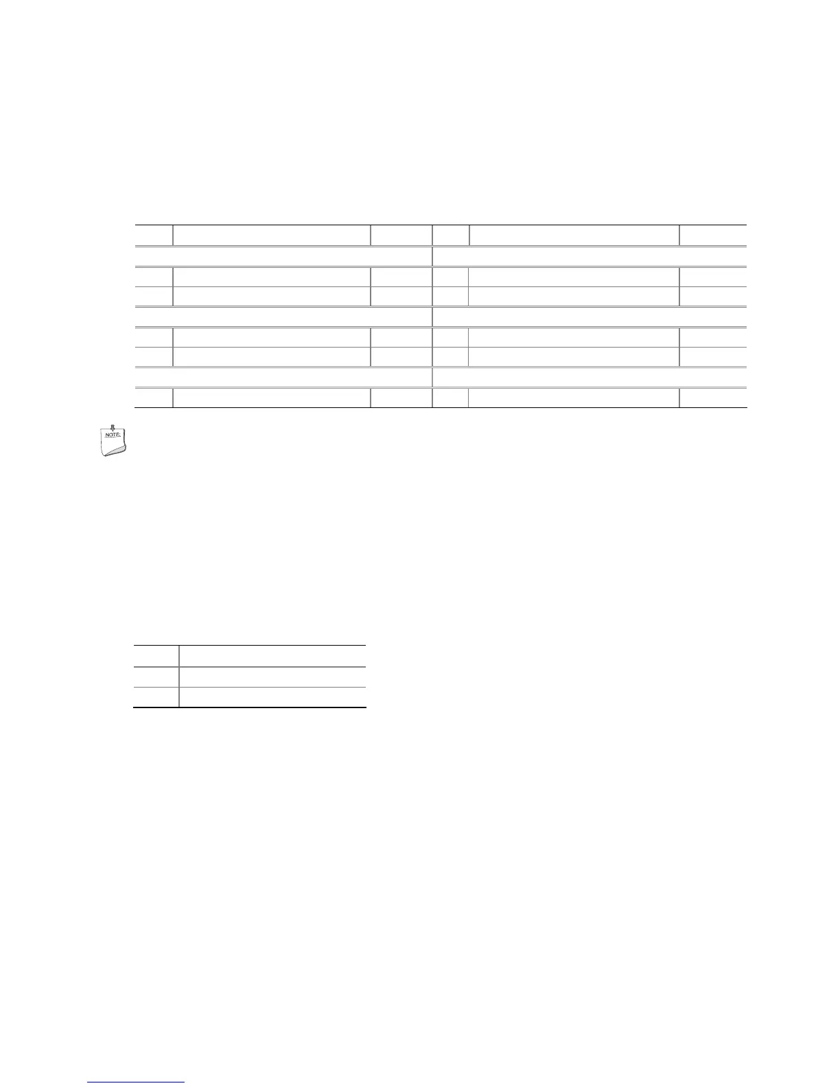
Table 10. Front Panel Header Signal Names
Pin Description In/Out
Pin Description In/Out
Hard Disk Drive Activity LED Power LED
1 Hard disk LED pull-up to +5 V
Out 2 Front panel LED+ Out
3 Hard disk active LED Out 4 Front panel LED- Out
Reset Switch On/Off Switch
5 Ground 6 Power switch In
7 Reset switch In 8 Ground
Power Not Connected
9 Power Out 10 No pin
NOTE
When connecting individual wires from your chassis front panel to the front panel
header, be sure to observe the connection polarity. Positive wires are usually solid
color and negative wires are usually white or striped.
Intel FCFH Header
Figure 21, G shows the location of the Intel FCFH header. Table 11 shows the pin
assignments and signal names for the Intel FCFH header.
Table 11. Intel FCFH Header Signal Names
Pin Description
1 Ground
2 FCFH#