Intel NUC D53427RKE Technical Product Specification
50
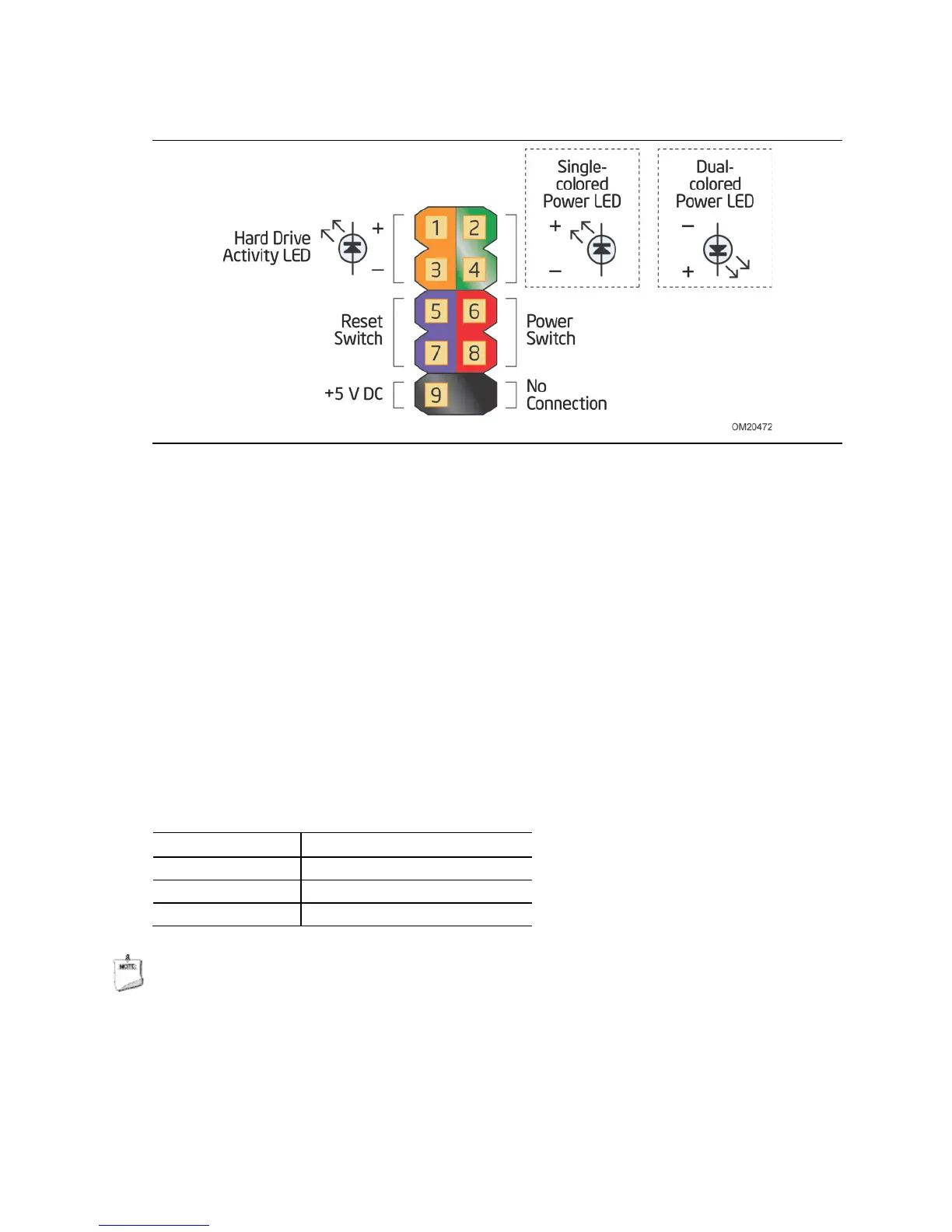
Figure 10. Connection Diagram for Front Panel Header
2.2.2.4.1 Hard Drive Activity LED Header
Pins 1 and 3 can be connected to an LED to provide a visual indicator that data is
being read from or written to a hard drive. Proper LED function requires a SATA hard
drive or optical drive connected to an onboard SATA connector.
2.2.2.4.2 Reset Switch Header
Pins 5 and 7 can be connected to a momentary single pole, single throw (SPST) type
switch that is normally open. When the switch is closed, the board resets and runs the
POST.
2.2.2.4.3 Power/Sleep LED Header
Pins 2 and 4 can be connected to a one- or two-color LED. Table 15 shows the
possible LED states.
Table 15. States for a One-Color Power LED
LED State Description
Off Power off
Blinking Standby
Steady Normal operation
NOTE
The LED behavior shown in Table 15 is default – other patterns may be set via BIOS
setup.
 Loading...