Intel Desktop Board DH57DD Product Guide
50
Front Panel USB 2.0 Headers
Figure 22, K shows the location of the front panel USB 2.0 headers and Table 18
shows its pin assignments and signal names.
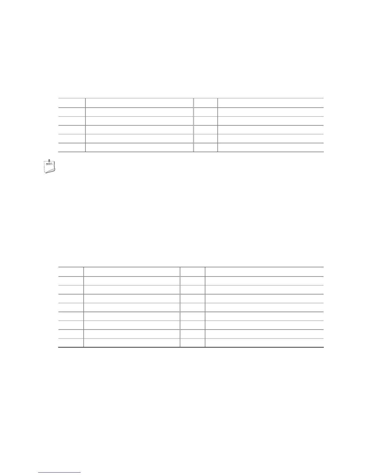
Table 18. USB 2.0 Header Signal Names
Pin Signal Name Pin Signal Name
1 Power (+5 V) 2 Power (+5 V)
3 D- 4 D-
5 D+ 6 D+
7 Ground 8 Ground
9 Key 10 No Connection
NOTE
Computer systems that have an unshielded cable attached to a USB port might not
meet FCC Class B requirements, even if no device or a low-speed USB device is
attached to the cable. Use a shielded cable that meets the requirements for a
full-speed USB device.
HD Audio Link Header
See Figure 22, L for the location of the HD Audio Link header. Table 19 shows the pin
assignments for the header.
Table 19. HD Audio Link Header Signal Names
Pin Signal Name Pin Signal Name
1 BCLK 2 Ground
3 RST# 4 3.3 Vcc
5 SYNC 6 Ground
7 SDO 8 3.3 Vcc
9 SDI0 10 +12 V
11 SDI1 12 Key
13 No Connection 14 3.3 V STBY
15 No Connection 16 Ground