Intel Desktop Board DQ965CO Product Guide
52
Connecting to the HD Audio Link Header
See Figure 25, H for the location of the HD Audio Link header. Table 10 shows the pin
assignments for the header.
Table 13. HD Audio Link Header Signal Names
Pin Signal Name Pin
Signal Name
1 BLCK 2 Ground
3 RST 4 3.3V/1.5V I/O
5 SYNC 6 Ground
7 SDO 8 3.3V_CORE
9 SDI 10 +12V
11 No connection 12 Key (no pin)
13 No connection 14 3.3V/1.5V STBY
15 No connection 16 Ground
Connecting to the Flexible Audio System
After installing the SigmaTel audio driver, the multi-channel audio feature can be
enabled.
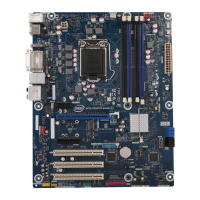
Figure 26 shows the back panel audio connectors. The default connector
assignments are shown in the table. The connectors are retaskable using the audio
driver interface.
Item Description
A Line in/retasking jack
B Line out/retasking jack
C Mic in/retasking jack
Figure 26. Back Panel Audio Connectors
 Loading...