Installing and Replacing Desktop Board Components
51
Chassis Intrusion Header
Figure 23, E shows the location of the chassis intrusion header. This header can be
connected to a mechanical switch on the chassis to detect if the chassis cover is
removed.
Table 10 shows the pin assignments and
signal names for
the chassis intrusion header.
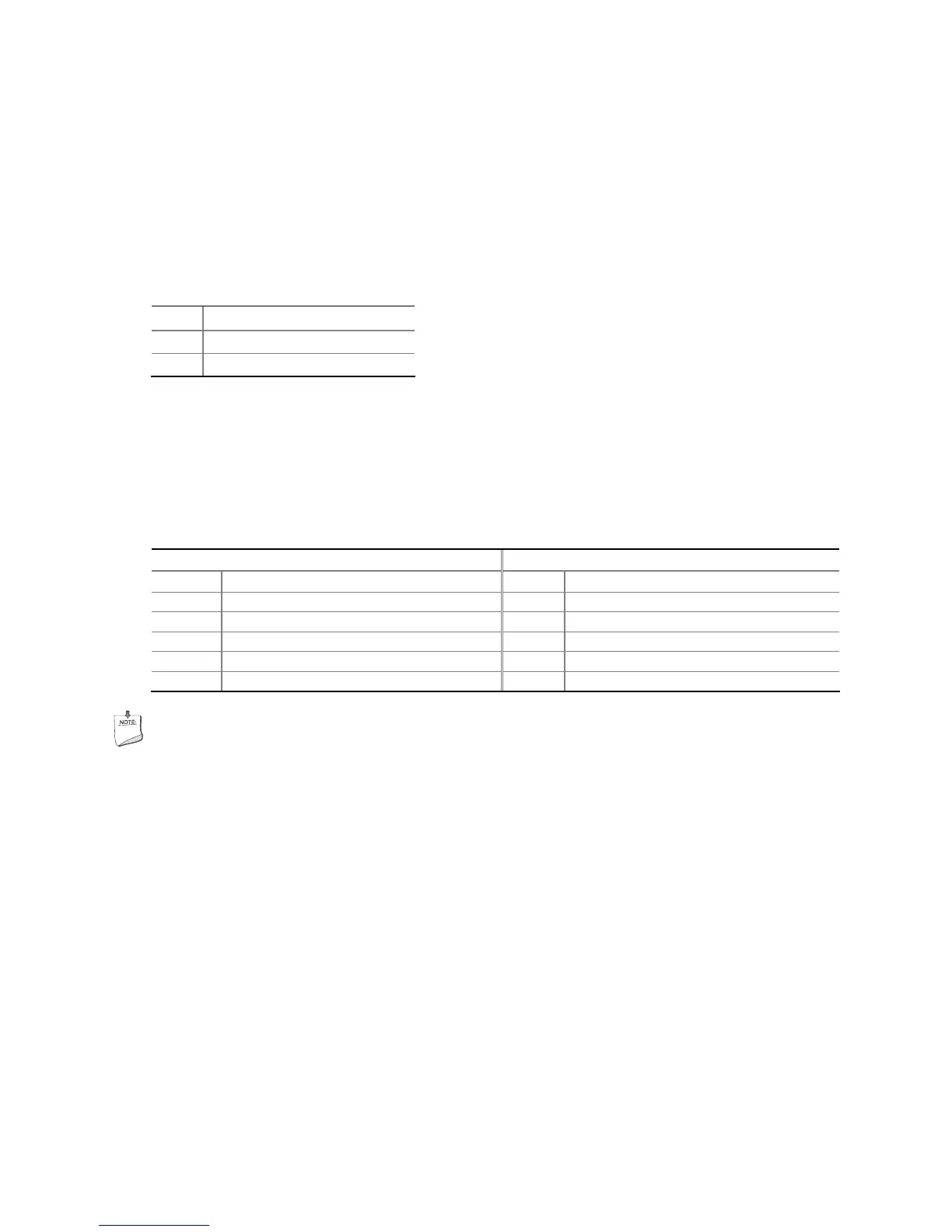
Table 10. Chassis Intrusion Header Signal Names
Pin Description
1 Intruder
2 Ground
USB 2.0 Headers
Figure 23, G shows the location of the USB 2.0 headers. Table 11 shows the pin
assignments and signal names for each USB 2.0 header. Each USB header can be
used to connect two USB devices.
Table 11. USB 2.0 Header Signal Names
USB Port A USB Port B
Pin Signal Name Pin Signal Name
1 Power (+5 V) 2 Power (+5 V)
3 D- 4 D-
5 D+ 6 D+
7 Ground 8 Ground
9 Key 10 No Connection
NOTE
Computer systems that have an unshielded cable attached to a USB port might not
meet FCC Class B requirements, even if no device or a low-speed USB device is
attached to the cable. Use a shielded cable that meets the requirements for a
full-speed USB device.