Contents
vii
4 Configuring Intel
®
Smart Response Technology and
RAID Using Intel
®
RST
Configuring Intel Smart Response Technology........................................................71
Configuring RAID ...............................................................................................72
Configuring the BIOS ..................................................................................72
Creating Your RAID Set ...............................................................................72
Loading the Intel RST RAID Drivers and Software (Required for
Microsoft Windows XP Installation) ..........................................................73
Setting Up a “RAID Ready” System ...............................................................73
A Error Messages and Indicators
BIOS Error Codes...............................................................................................75
BIOS Error Messages..........................................................................................76
Port 80h POST Codes..........................................................................................77
B Regulatory Compliance
Safety Standards ...............................................................................................81
Battery Caution ..........................................................................................81
European Union Declaration of Conformity Statement..............................................82
Product Ecology Statements ................................................................................83
Recycling Considerations .............................................................................83
China RoHS ...............................................................................................86
EMC Regulations ................................................................................................87
FCC Declaration of Conformity......................................................................87
Canadian Department of Communications Compliance Statement......................88
Japan VCCI Statement ................................................................................88
Korea Class B Statement .............................................................................89
Ensure Electromagnetic Compatibility (EMC) Compliance..................................89
Product Certifications..........................................................................................90
Board-Level Certifications ............................................................................90
Chassis- and Component-Level Certifications..................................................91
Chassis and Component Certifications............................................................91
ENERGY STAR*, e-Standby, and ErP Compliance ....................................................92
Figures
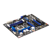
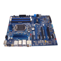
1. Intel Desktop Board DZ68ZV Components........................................................12
2. LAN Connector LEDs .....................................................................................19
3. Location of the Back to BIOS Button................................................................23
4. Onboard Power and Reset Buttons ..................................................................27
5. Location of the Processor and Voltage Regulator LEDs........................................28
6. Location of the Board Status LEDs ..................................................................30
7. Installing the I/O Shield ................................................................................33
8. Intel Desktop Board DZ68ZV Mounting Screw Hole Locations..............................34
9. Unlatch the Socket Lever...............................................................................35
10. Lift the Load Plate.........................................................................................36
11. Remove the Processor from the Protective Cover ..............................................37
12. Install the Processor .....................................................................................37
13. Secure the Load Plate in Place........................................................................38
14. Connecting the Processor Fan Heat Sink Power Cable to the
Processor Fan Header....................................................................................39