EasyManuals Logo

Intel Galileo Hardware Guide

Intel Galileo
34 pages
To Next Page IconTo Next Page
To Previous Page IconTo Previous Page
Page #15 background imageLoading...
Page #15 background image
Hardware 15
Hardware
For most inputs (potentiometers, thermsistors, photodiodes, phototransistors) you need to connect both the
input and a resistor. They are all connected in a similar conguration, which is called a voltage divider.
If you just had the sensor by itself, all the electricity would have to ow through it, regardless of how much
resistance it had. With another resistor, the electricity is split up, it is divided, between the analog pin and the
constant resistor. The less resistance your sensor has the more electricity will go through the resistor.
3.4: Using pinMode
We are now no longer using outputs, we are using inputs. This means we have to change how we use pin-
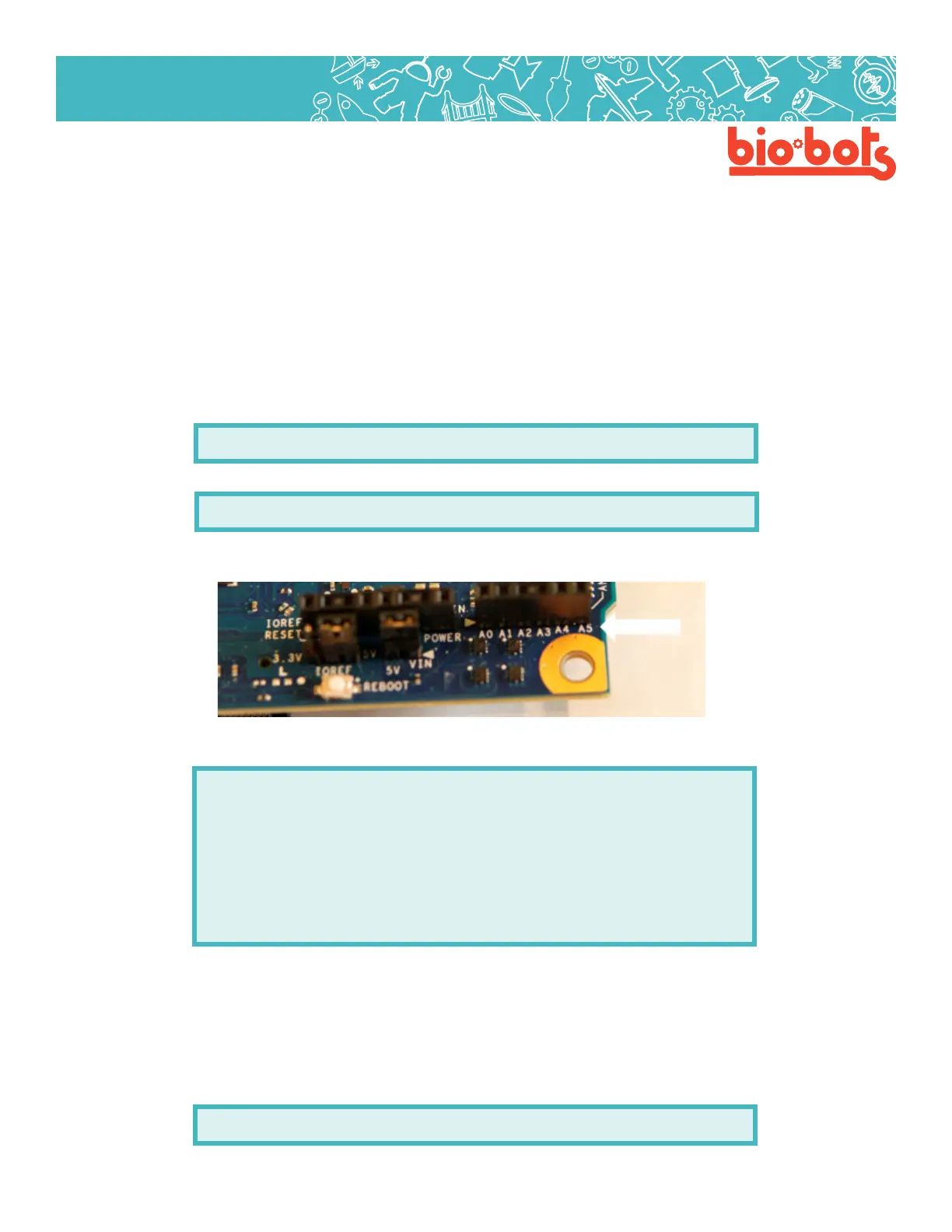
Mode. In the setup routine we have to choose what pin we are inputting into, the pins available are A0, A1,
A2, A3, A4 (Lesson 3, Figure 4). If we are using A0 it can be written as:
pinMode(A0,INPUT);
Or it can be written as:
pinMode(0,INPUT);
Writing the ‘A makes it more clear that it is the A0 pin, as opposed to the 0 pin which can only handle digital
information.
Lesson 3, Figure 4
Within the program it would look like this:
voidsetup(){
pinMode(A0,INPUT);
//usepinA0asananaloginput
}
voidloop(){
//dostu…
}
3.5: Using analogRead and Creating a Variable
If we want to use our input, we have to read from the pin. And we have to be able to use the information we
read out from our pin. The microcontroller reads the pin and gives you a number between 0 and 1023, which
represents between no voltage and full voltage.
The function to read from an analog pin is analogWrite, which may look like this:
analogRead(A0);

Other manuals for Intel Galileo

Questions and Answers:

Question and Answer IconNeed help?

Do you have a question about the Intel Galileo and is the answer not in the manual?

Intel Galileo Specifications

General IconGeneral
Product familyIntel Galileo
Product seriesIntel Galileo board
Processor cache16 KB
Processor cores1
Processor modelIntel Quark SoC X1000
64-bit computingNo
Processor socketQuark 393pin FCPGA
Product codename-
Processor frequency400 MHz
Microcontroller modelIntel Quark
Processor lithography32 nm
Processor manufacturerIntel
Thermal Design Power (TDP)12.5 W
Memory bandwidth supported by processor (max)2.5 GB/s
Memory bus32 bit
Flash memory8 MB
Memory channelsSingle-channel
Flash memory typeNorwegian
Memory clock speed800 MHz
Internal memory typeDDR3
Number of DIMM slots0
Compatible memory cardsMicroSD (TransFlash), MicroSDHC
Maximum internal memory0.256 GB
Maximum memory card size32 GB
SRAM (Static Random Access Memory)512 KB
EEPROM (Electrically Erasable Programmable Read-Only Memory)8 KB
USB version2.0
Ethernet LANYes
USB ports quantity3
Ethernet interface typeFast Ethernet
ARK ID78919
StatusDiscontinued
Launch dateQ4'13
Package size15 x 15 mm
FSBs supportedNA
Processor includedIntel® Quark™ SoC X1000 (16K Cache, 400 MHz)
Supported memory typesDDR3-SDRAM
Power over Ethernet (PoE) voltage12 V
Export Control Classification Number (ECCN)4A994
PCI SupportPCI Express
PCI Express interface data lanesx1
Form factorArduino
Market segmentDesktop
DC input voltage5 V
Intel Small Business Advantage (SBA) version0.00
Last change63903513
Processor ID79084
Product type11
Harmonized System (HS) code8471500150
Weight and Dimensions IconWeight and Dimensions
Width- mm

Related product manuals