NVM Information Guide—ICH8/ICH9
26
1.5.1 PHY Extended Configuration (Words 00h – (2N-1)h From Base)
There are N valid Dwords in this range, where N = number of PHY Dwords as
determined in the Extended LCD Length field. Ta b l e 2 2 lists the structure of each
Dword.
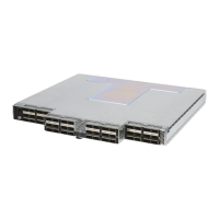
Table 22. PHY Extended Configuration (Words 00h – (2N-1)h From Base)
1.5.2 Dock Extended Configuration (Words (2N)h – (2N+2L-1)h From
Base)
There are L valid Dwords in this range, where L = number of Dock Dwords as
determined in the Extended Dock Length field. The structure of each entry is the same
as in the PHY Extended Configuration listed in Ta b l e 2 2 .
1.5.3 Undock Extended Configuration (Words (2N+2L)h – (2N+4L-
1)h From Base)
There are L valid Dwords in this range, where L = number of Undock Dwords as
determined in the Extended Dock Length field. The structure of each entry is the same
as in the PHY Extended Configuration listed in Ta b l e 2 2 .
Bit Name Default Description
31:21 Reserved 00h Reserved
20:16 Register 00h
Contains the address of the PHY register to write to. A value of
1Fh indicates that this is a command to switch to another MDIO
page.
15:0 Data 00h
Data to be written to the PHY register. When the register field
above equals 1F, the Data field indicates the page number to
switch to. Note that the page number should be programmed to
the 11 MSB while bits 4:0 should be set to 00h.