Datasheet 97
Electrical Specifications
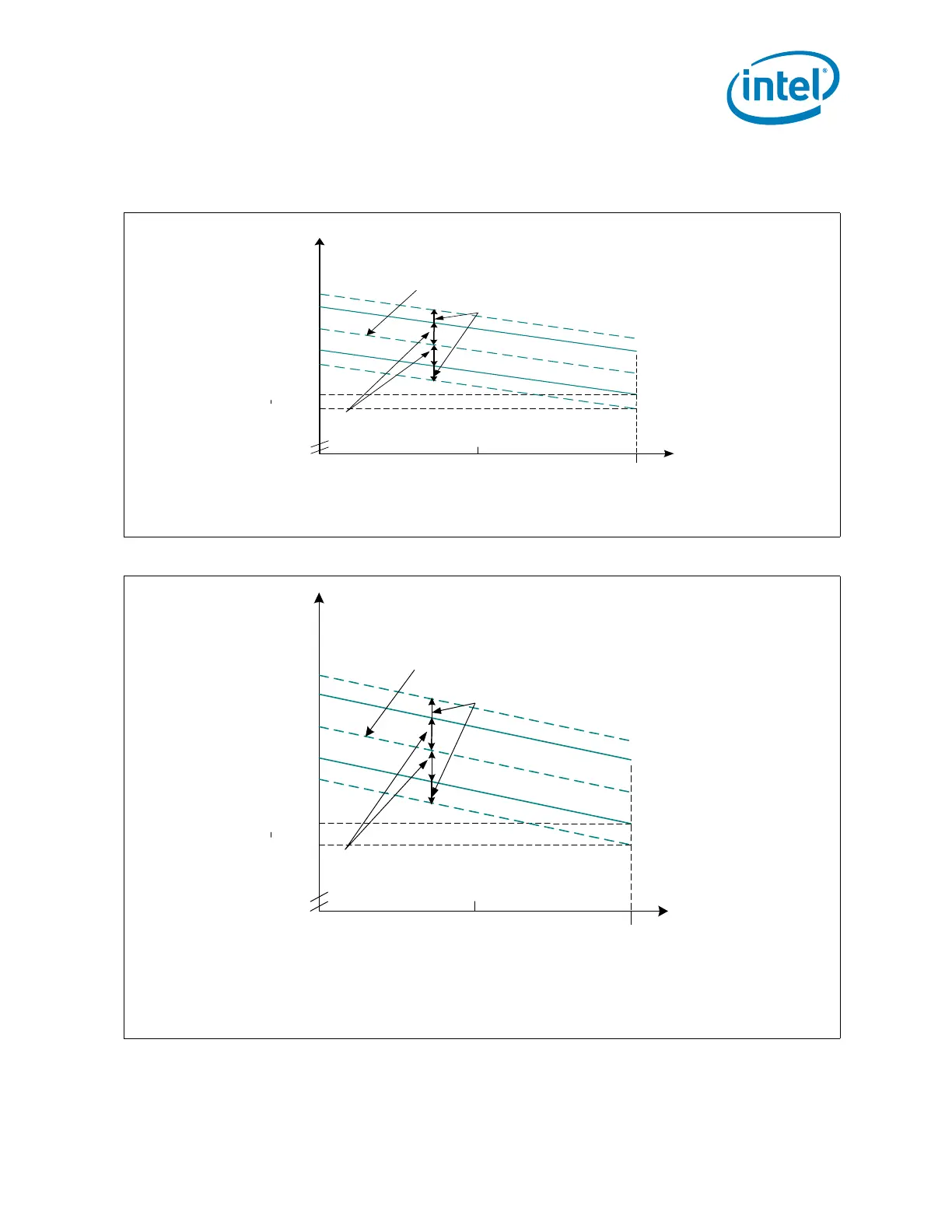
Figure 7-13.Active V
CC
and I
CC
Loadline (PSI# Asserted)
Figure 7-14.Active V
CC
and I
CC
Loadline (PSI# Not Asserted)
[
V
CC
nom
± V
CC
Tolerance
= VR St. Pt. Error
V
CC, D C
min
V
CC, D C
max
V
CC
max
V
CC
min
13mV= RIPPLE
I
CC
[A]
0
Slope = SLOPE
LL
VCC_SENSE, VSS_SENSE pins.
D iffere ntia l R em o te S en se re qu ired .
V
CC
S e t P o in t E rro r T o le ra n ce is per b e lo w :
Tolerance V
CC-CORE
VID Voltage Range
--------------- -------------------------------------------------------
± [VID*1.5%-3mV] V
CC
> 0.7500V
± [11.5m V-3mV] 0.5000V<V
CC
= 0.7500V
[
]
V
CC
nom
± V
CC
Tolerance
= VR St. Pt. Error
V
CC, DC
min
V
CC, DC
max
V
CC
max
V
CC
min
10mV= RIPPLE
I
CC
[A]
0
Slope = SLOPE
LL
VCC_SENSE, VSS_SENSE pins.
Differential Remote Sense required.
V
CC
Set Point Error Tolerance is per below:
Tolerance V
CC-CORE
VID Voltage Range
--------------- -------------------------------------------------------
± [VID*1.5%] V
CC
> 0.7500V
± [11.5mV] 0.5000V < V
CC
=0.7500V
 Loading...


