Hardware VIII XLR choice : 3 or 5 pins
VIII XLR choice : 3 or 5 pins
The "DMX" norm imposes 5-pin XLR but the use of 3-pin XLR is very widespread because of their cost.
Our interfaces are available either in 3-pin or 5-pin. You can change the XLR connector if you want. To
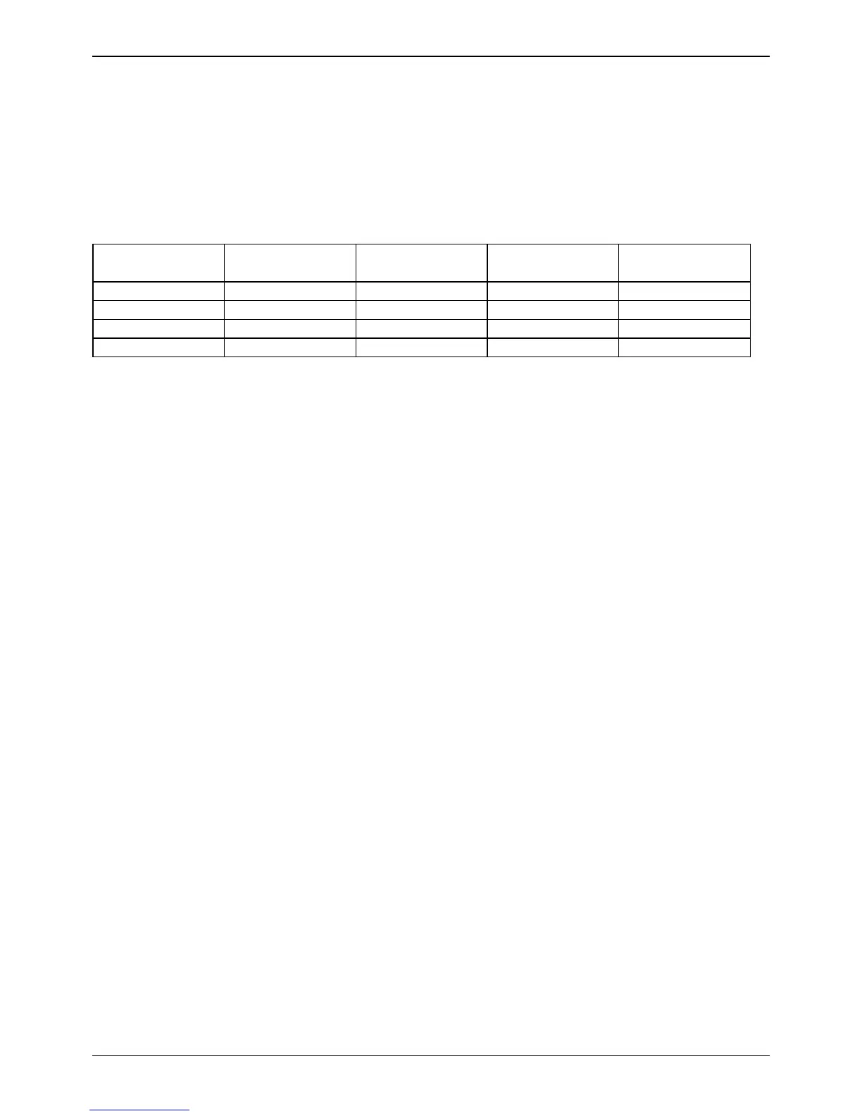
do so, there are 4 resistors that must be removed or not. See the table below:
RSC (R5) 0 ohms RSD (R8) 0 ohms RSB (R30) 0 ohms RSA (R31) 0 ohms
XLR Female 3 pins
XLR Female 5 pins YES YES
XLR Male 3 pins YES YES
XLR Male 5 pins YES
Caution:
You can not transform a "DMX OUT" interface in a "DMX IN" interface (or vice-versa) just by replacing
the XLR connector.
XLR Connector Pin Assignment :
Pin1 : DMX OUT GROUND
Pin2 : DMX OUT DATA -
Pin3 : DMX OUT DATA +
SIUDI5 interfaces
The references are RSC1, RSD1, RSB1, RSA1 (DMX output) and RSC2, RSD2, RSB2, RSA2 (DMX
input).
Page 11