- 22 -
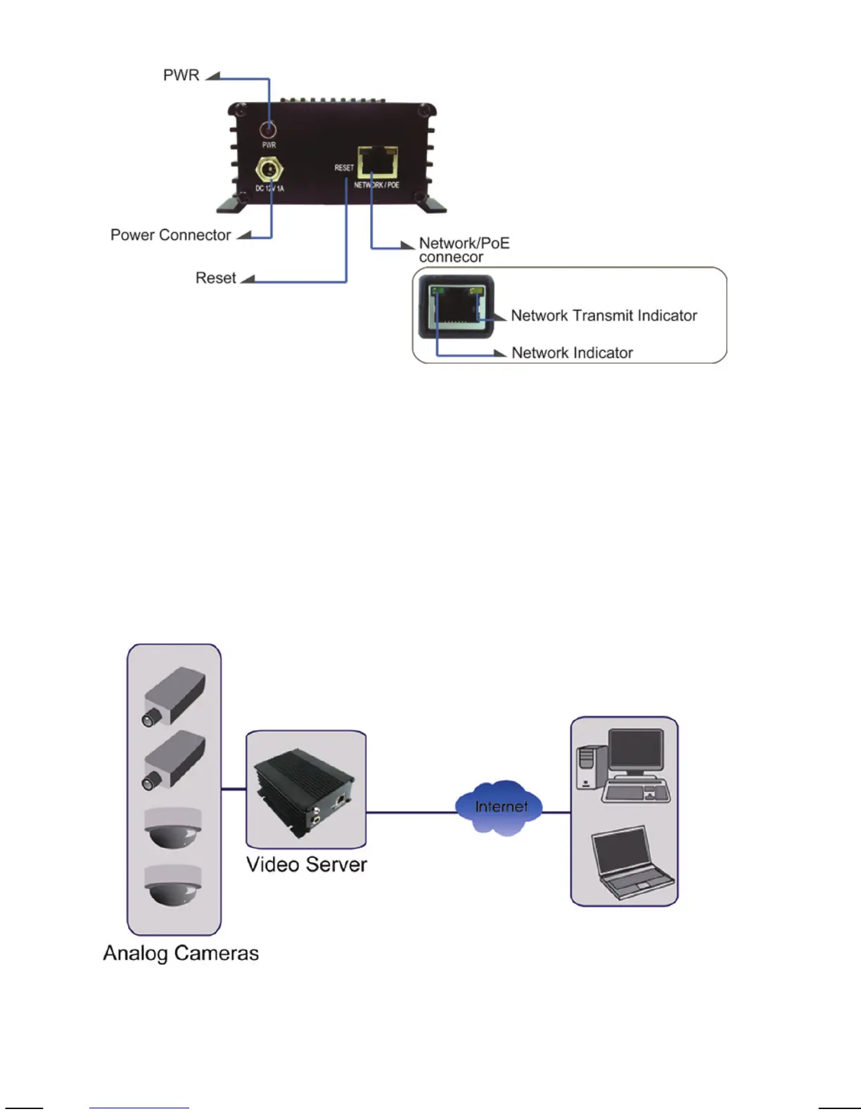
Rear
PWR: LED lights up once the network video server has
successfully started up.
Power Connector: Connect the power adapter here, unless you wish to
utilize the Power over Ethernet functionality.
Network / PoE Connector: Standard RJ45 socket for Cat5 (or better) network
cable. IEEE 802.3af-compatible input sources are
supported.
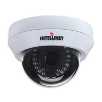
Connection Diagram
Note: The NVS30 is a one-channel video server. Only one CCTV camera can be
connected at a time.