EasyManuals Logo

Intellinet NVS30 User Manual

Intellinet NVS30
115 pages
To Next Page IconTo Next Page
To Previous Page IconTo Previous Page
Page #23 background imageLoading...
Page #23 background image
- 23 -
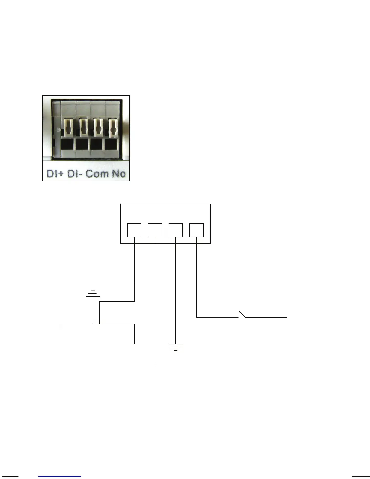
3.2 Digital I/O Terminal Block Connector
The Network Camera and Network Video Server, with the exception of the
NSC15 models, are equipped with a digital I/O interface. It can be used to
connect external alarm sensors (pins 1 and 2) or to power external devices
(pins 3 and 4).
From left to right: Pins 1 (DI+), 2 (DI-), 3 (Com) and 4 (No)
DI+: Digital Input (+), DI-: Digital Input GND (-)
Com: Power DC 12 V (+), No: Power GND (-)
The NVS30 Network Video Server features two additional pins 5 (+) and 6 (-)
that are used to connect analog CCTV camera with PTZ control (RS-485).
Ground
Ground
12 V
Alarm out device
12 V
Max. 30 W
Switch
NO COM DI- DI+

Other manuals for Intellinet NVS30

Questions and Answers:

Question and Answer IconNeed help?

Do you have a question about the Intellinet NVS30 and is the answer not in the manual?

Intellinet NVS30 Specifications

General IconGeneral
BrandIntellinet
ModelNVS30
CategorySecurity System
LanguageEnglish

Related product manuals