1485 Jacobs Rd.
Deland, FL 32724
386.738.7307
P/N 53-00912-000 Rev. D 080919
www.intellitec.com
Intellitec
INSTALLATION & SERVICE MANUAL
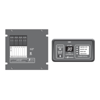
30A SMART ENERGY MANAGEMENT SYSTEM
TM
MODEL 500A
FUSES
DO NOT
EMS CONTROL MODULE PLUGS, PINS, AND FUNCTIONS:
F1
J1 = 2 pin Molex KK-100 connector - HI-POT TEST Power Up
J2 = 3 pin Amp Mate-n-Lok connector - Power Connector
J3 = 2 pin Molex KK-156 - Current Sensor Connector
J4 = 6 pin Amp Mate-n-Lok connector - Control Relays5&6contacts
J5 = 4 pin AMP Mate-n-Lock - Communications Connector to Display Panel and/or external PMC, or
RV/PMC Systems.
- 5 Amp ATO type, for EMS Control Module circuitry only. . This
could result in severe damage to the circuitry or create a possible fire hazard.
1 Hi-Pot Override
2 Hi-Pot Override
1 +12 Volts Supply
2 +12V Gen Set Run Input
3 Chassis Ground
1 Current Sensor Input
2 Current Sensor Input
1 Relay 5 N.O.
2 Relay 5 COM.
3 Relay 5 N.C.
4 Relay 6 COM.
5 Relay 6 N.C.
6 Relay 6 N.O.
1 Power
2 Data In
3 Ground
4 RV/PMC Master Out
replace with a fuse of higher rating
Pin Function
Pin Function
Pin Function
Pin Function
Pin Function