1485 Jacobs Rd.
Deland, FL 32724
386.738.7307
P/N 53-00912-000 Rev. D 080919
www.intellitec.com
Intellitec
INSTALLATION & SERVICE MANUAL
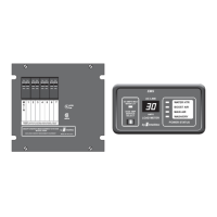
30A SMART ENERGY MANAGEMENT SYSTEM
TM
MODEL 500A
PERFORMANCE TEST
CIRCUIT BREAKERS
The system is now ready for testing.
At the installers preference, to assure there are no potential shorts, a Hi-Pot test can be performed on the installation.
To do this, +12 volts must be applied to the system. A jumper wire must be installed to tie the two pins of the "Hi-Pot
Test" plug, J1, to turn the system on without the presence of 120 volt power. This plug is located on the right side of
the EMS Control module The relays on the module should be heard clicking as they pull in.
(If the system is equipped with a Display Panel, the LED's should light and the numeric display should read "0".) The
Hi-Pot test should now be conducted in accordance with standard procedures for the tester being used. Assuming
the system passes, the covers should be taken off and the jumper removed from J1. If not, the problem must be
corrected before proceeding further.
All the 120 volt loads should be turned off or disconnected. Both 120 volt AC and 12 volt DC power should now be
applied to the system. When this is done, the relays should be heard pulling in, one at a time, at one-second
intervals.. If the system is equipped with a Display Panel, the numeric display should read "0" and the four LED's
should be come in order. If the system is not equipped with a display panel, a clamp-on type ammeter should be
used to measure the current being supplied by the 30Amp shore power cord.
Connect or turn on one of the controlled AC loads. It should operate and the numeric display or the clamp-on
ammeter should show the amount of current that load is drawn. Turn that appliance off and repeat this with each of
the others.
To test the load shedding, turn on all the controlled appliances. The total current drawn should exceed 30 Amps. (If
not, add additional loads to the non-controlled receptacles.) When the total amount of current exceeds 30 Amps,
the loads should begin to turn off to bring the total below 30 Amps.
There are 4 positions for the circuit breakers in the box. The circuit breakers can be single, or dual types.
One must be a 30 Amp to be used as the Main Breaker.
The following breakers are suitable for MAIN and BRANCH breakers:
Bryant - BR, BD, GFCB, Filler Plate FP-1B
ITE Gould - QP, QT, Filler Plate Qf3
Hi-POT TEST
SYSTEM TEST
(See top view drawing.)
 Loading...