1485 Jacobs Rd.
Deland, FL 32724
386.738.7307
P/N 53-00912-000 Rev. D 080919
www.intellitec.com
Intellitec
INSTALLATION & SERVICE MANUAL
30A SMART ENERGY MANAGEMENT SYSTEM
TM
MODEL 500A
Finally, on the Control Module, there is a small 2 pin plug labeled J1 which is only used for the High Pot Test on
the system. When the two pins are shorted together, the EMS will operate without the presence of 120 VAC.
Now the should be moved into the mounting hole, being careful not pinch any of the wires. It should be screwed
in place using four # 8, round head screws into the 4 holes in the side flanges. The front cover should be secured into
place with the 6 screws provided in the holes in the top and bottom flanges.
The Display Panel is equipped with a six inch long pigtail with a 3-pin
Mate-N-Lock female connector. An extension harness up to 100 feet
long can be attached between the Display Panel and the EMS Control
Module, with a 3-pin male Mate-N-Lock plug at the Display Panel end
and a 4-pin male Mate-N-Lock plug at the Control Module end.
The wiring of the plug at the Control Module end determines the system
configuration as follows:
1)
Pins 1 thru 3 on the 3-pin plug connect to the corresponding pins on the 4-pin plug.
2)
Pins 1 thru 3 on the 3-pin plug connect to corresponding wires in the RV Multiplex system and the corresponding
pins on the 4-pin plug. The consumes Modules A, B, and C signals for communications,
therefore, no other devices in the system may be assigned as these Modules.
3)
Pins 1 thru 3 on the 3-pin plug connect to the corresponding pins on the 4-pin plug. Remove jumper JU-1 on the
low voltage side of the Control Module printed circuit board. The consumes Modules A, B,
and C signals for communications, therefore, no other devices in the system may be assigned as these Modules.
The Display Panel should be plugged onto the mating three-pin Mate-N-Lock connector in the harness, insuring that
it is fully seated and locked. The panel should then be installed in the hole and screwed in place using two # 6, flat
head screws through the holes in the panel. A white function label should be lettered to correspond to the order of
load shedding and installed behind the cover label. The cover label should be placed against the front panel and the
trim bezel snapped on to hold the label in place.
EMS
Stand-Alone Mode
RV Multiplex Master Mode
30A SMART EMS
PMC Mode
30A SMART EMS
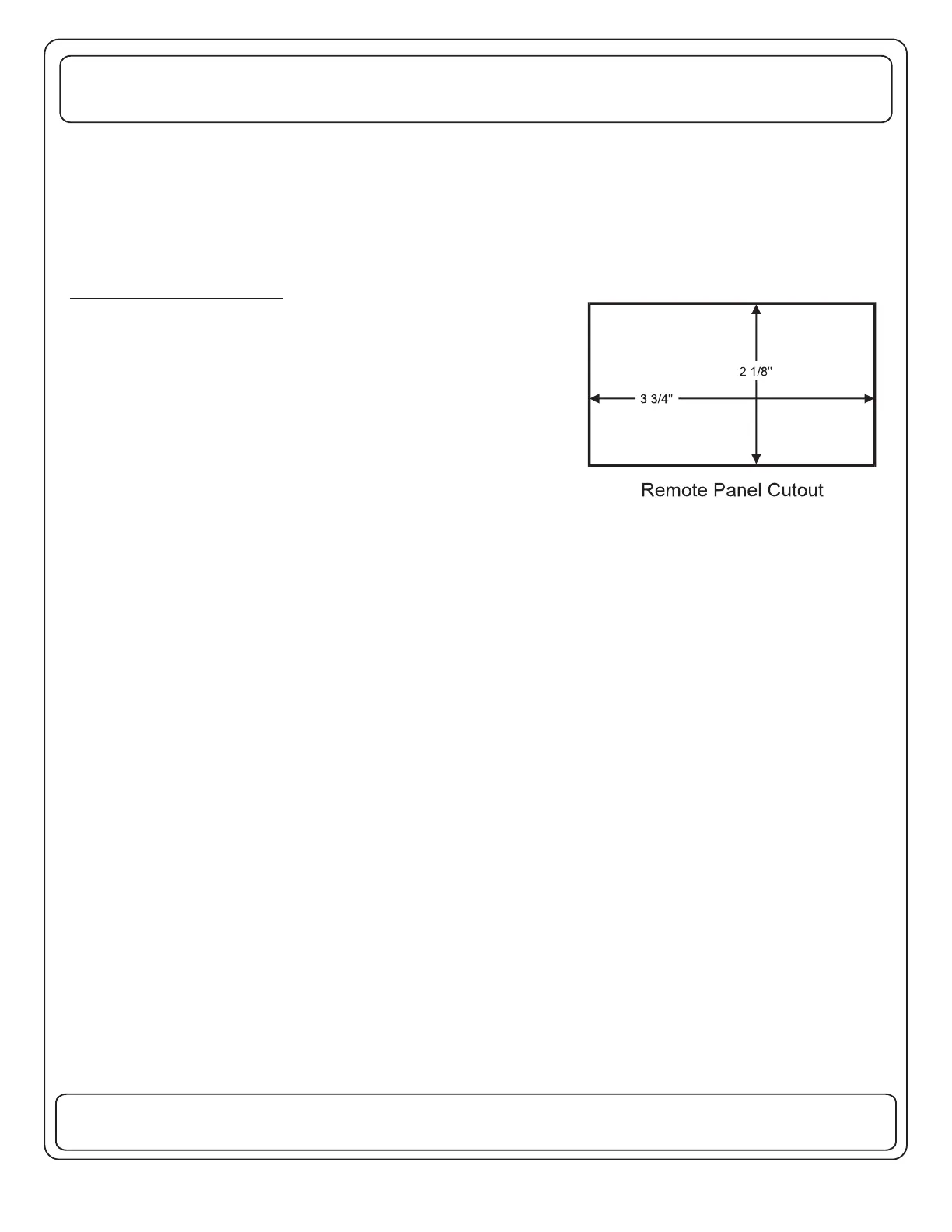
OPTIONAL REMOTE PANEL
If a remote Display Panel is to be used in the installation, it should be
installed now. Select a convenient location for the panel, where it can
be easily viewed by the owner. Cut a hole for the panel as shown.
TM
TM
 Loading...