1485 Jacobs Rd.
Deland, FL 32724
386.738.7307
P/N 53-00912-000 Rev. D 080919
www.intellitec.com
Intellitec
INSTALLATION & SERVICE MANUAL
30A SMART ENERGY MANAGEMENT SYSTEM
TM
MODEL 500A
CONTROLLED LOADS
EMS
the Load Meter indicates the amount of current actually being drawn
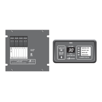
The system offers control of up to four 120 VAC powered loads. Loads that are to be controlled are connected to one of
the relay circuits of the . There are five total control relays in the EMS. ONLY 4 of these can be used in a given
application.
Two of these five circuits have single-pole double-throw, low voltage relays, with un-dedicated contacts available.
These are intended to control air conditioners, or other appliances equipped with low voltage controls, or thermostats.
The contacts of the relays are typically wired in series with the thermostats of air conditioners, so the EMS turns off only
the compressor. This leaves the fan on to re-circulate the air, masking the interruption of the compressor. These relay
circuits could also control other 120 volt appliances, if an additional control relay is added externally.
Three of these circuits are 15 Amp relays to interrupt the 120 volt power to the loads. These circuits are intended to
control 120 volt appliances such as water heater, washer/dryer, coffee maker, etc. For the 120 switched loads, power is
routed from the individual branch circuit breakers to one of these 120 volt relays. The controlled load is then fed from
that relay.
In operation, when the 120 VAC and 12 VDC are initially applied, the system will energize the relays at one second
intervals, closing the normally-open contacts on each of the five relays while monitoring the total current. If the total
should exceeds the service limit, the system will turn off the last load that was turned on. As it does this, it calculates the
amount of current that was removed, which is the value for that load. This value is placed in memory. The system has
"learned" the amount of current that particular appliance draws. This feature compensates for the differences in current
draw over a range of line voltage and ambient temperature, by re-learning the load each time it is turned off.
The system now waits until the total current is lower than the service limit, by the amount in memory, before it will turn
that load back on. This assures that there is sufficient current to operate the load.
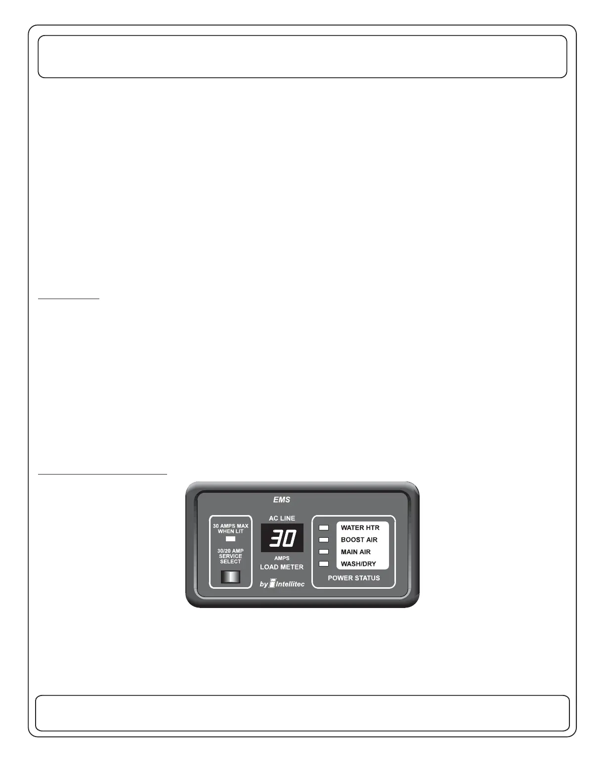
The optional display panel, can be mounted remotely and connects to the main unit with a small gauge, three wire
cable.
Four Power Status LED's indicate power is applied to those loads. These LED's are on when the power is applied. A
two digit display, , by all the appliances in the
coach.
OPERATION
NOTE: two-minute minimum delay ,There is a period after a load is shed before the load can be turned back on
again to prevent air conditioners from turning on with a head of pressure. During this delay period, if there is enough
current available to energize the load, the LED status indicator for that load will flash. After the delay period expires, the
load will be energized and the indicator will turn on.
OPTIONAL DISPLAY PANEL
 Loading...