1485 Jacobs Rd.
Deland, FL 32724
386.738.7307
P/N 53-00912-000 Rev. D 080919
www.intellitec.com
Intellitec
INSTALLATION & SERVICE MANUAL
30A SMART ENERGY MANAGEMENT SYSTEM
TM
MODEL 500A
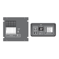
The “Service Select” button allows the service type to be set to either 30 Amps
or 20 Amps, to match the incoming service. If the pictured adaptor is used on the
incoming service, press the “Service Select” button to select the 20 Amp mode.
When power is first applied, the system will always be in the 30Amp mode.
The 30/20 Amp indicator LED will be ON when the system is in the 30Amp mode.
Momentarily pressing this button will switch the system to the 20 Amp mode.
Momentarily pressing this button again, will switch the system back to the
30Amp mode.
This panel can also be used to display the value of current stored in memory for each of the four loads. To
display the values of current stored in memory for each of the four loads, push and hold the “Service Select”
button for a minimum of 2 seconds and release it. The last selected load LED will illuminate and the stored
value will appear on the Load Meter. Pushing “Service Select” again, will cycle to the next load. If the unit is in
the three-hour averaging mode, indicated by a lit decimal point at the lower right corner of the Load Meter, the
display will cycle to display average current when no load LED’s are lit. If a period of 5 seconds elapses
between button presses, the Load Meter will return to normal operation and display total current draw.
The first step when installing an EMS, is to determine which loads will be controlled and in what order they will be
shed. A typical scheme would be to control the two air conditioners, the water heater, and the washer/dryer. With
these loads, the first load to be shed should be the water heater, as its loss of operation would be the least noticed. It
would switch to operate on gas if needed. The next would be the bedroom air. The third would be the washer dryer
and finally the main air. Choosing this sequence would provide the least inconvenience to the occupants.
INSTALLATION
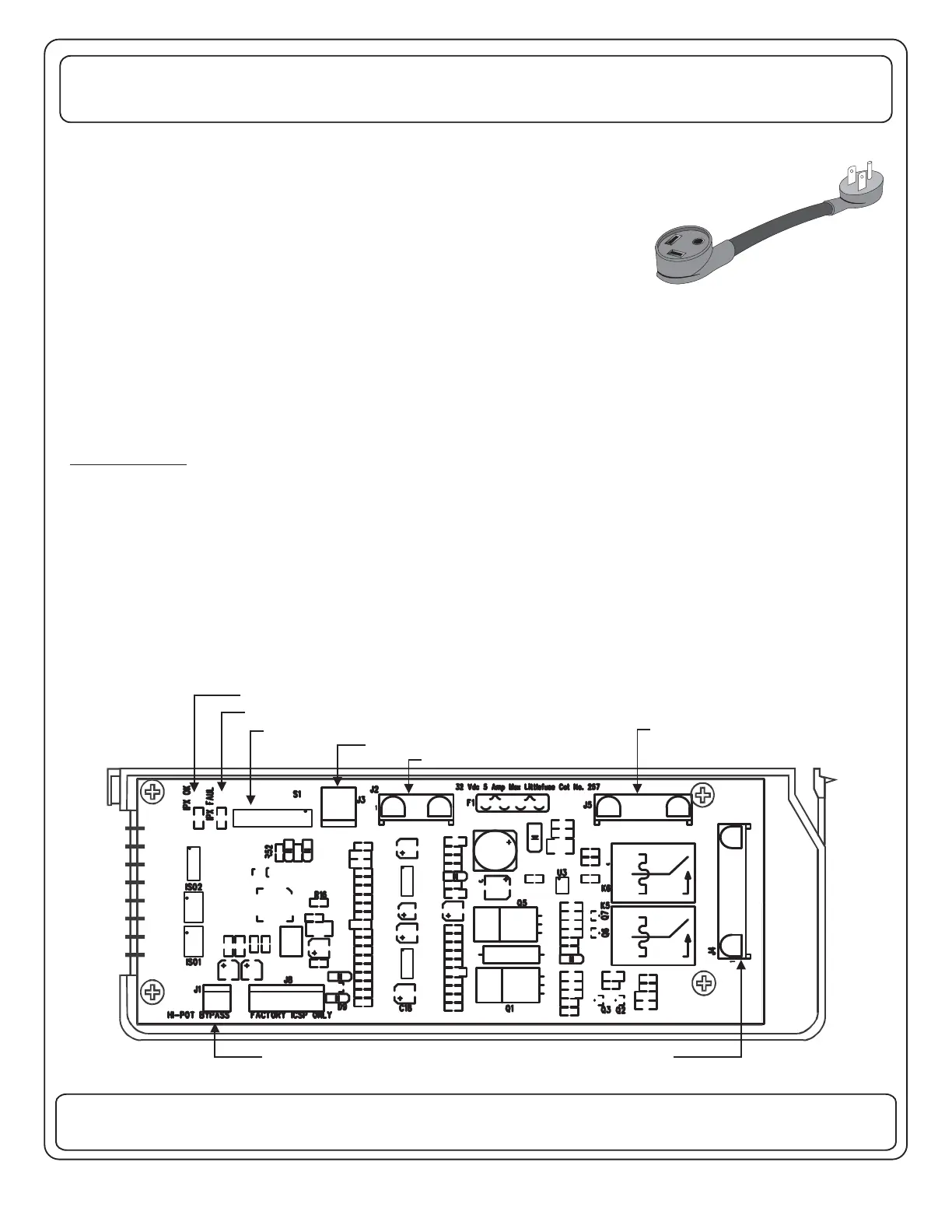
The EMS Control Module has an eight position dip-switch (S1) on the board to configure the features active in the
system. The switches in positions 1 thru 3 determine the order of shedding of the loads (See next page). Placing the
switch in position 4 in the “OFF” position enables the energy management feature when the gen set is running and
the setting of the switch in position 5 determines the service rating when the gen set is running. If the switch in
position 5 is in the “ON” position the service limit is 20 Amps (2.5kW), if it is “OFF” the service limit is 30 Amps (3.6kW).
Additional switches in positions 6 thru 8 are reserved for future control configurations.
87654321
CONFIGURATION DIP SWITCH (Factory Default=POS. 1-5 On)
COMMUNICATIONS FAILURE IND.
COMMUNICATIONS OK IND.
HI-POT BYPASS JUMPER
POWER CONNECTOR
CURRENT TRANSDUCER INPUT
COMMUNICATION CONNECTOR
TO DISPLAY PANEL and/or PMC or
RV/PMC SYSTEM
LOW VOLTAGE RELAY OUTPUTS
30 AMP EMS CONTROL MODULE - LOW VOLTAGE CONNECTION SIDE
 Loading...