1485 Jacobs Rd.
Deland, FL 32724
386.738.7307
P/N 53-00912-000 Rev. D 080919
www.intellitec.com
Intellitec
INSTALLATION & SERVICE MANUAL
30A SMART ENERGY MANAGEMENT SYSTEM
TM
MODEL 500A
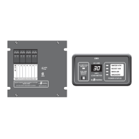
J6 = 5 Position Terminal Block
J7 = 2 Position Terminal Block
NOTE: J6 and J7 terminal blocks - Will accept up to 12 GA or 14 GA copper wire ONLY.
Term Function
Term Function
1 From Circuit Breaker for Relay 2
2 Output of Relay 2
3 From Circuit Breaker for Relay 1
4 Output of Relay 1
5 Neutral
1 Output of Relay 3
2 From Circuit Breaker for Relay 3
Trouble Shooting
If the following problems occur, proceed with their analysis .
A. Check incoming power source.
1. Make sure the shore power cord is plugged into the outlet.
2. Check the circuit breaker at the shore power outlet to be sure it is set.
Turn it off and then back on to be sure.
3. Check the 30 Amp Main circuit breaker in the EMS box to be sure it is set.
Turn it off and then back on to be sure.
4. Using a circuit checker, be sure the 30 Amp shore power outlet has 120 volts available.
B. Check Change-Over relay, if so equipped.
1. Measure the voltage at the incoming side of the Main 30 Amp breaker. If voltage is NOT the same as
the incoming line, repair the change-over.
A. Check the 12 volt power to the EMS module.
1. Check 12 volt fuse in 12 volt Distribution Panel. Replace if necessary.
2. Check 12 volt, 5 Amp fuse on EMS Module. Replace if necessary.
in the order in which the steps are listed
(Refer to the change-over service literature for trouble
shooting.)
I. No 120 volt appliances working.
II. 120 volts available at non-controlled appliances and receptacles.
Controlled appliances do not operate.
TM
TM
TM
 Loading...