1485 Jacobs Rd.
Deland, FL 32724
386.738.7307
P/N 53-00912-000 Rev. D 080919
www.intellitec.com
Intellitec
INSTALLATION & SERVICE MANUAL
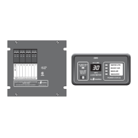
30A SMART ENERGY MANAGEMENT SYSTEM
TM
MODEL 500A
B. Check 120 volt circuit breakers in EMS
1. Reset circuit breakers if necessary.
2. Check for presence of voltage at branch circuit breakers with voltmeter.
3. Check for presence of voltage at EMS terminals with voltmeter.
4. Check wire from EMS odule to neutral bar is installed.
A. Check thermostat wiring and settings.
B. Check air conditioner
A. Check dip-switch setting per Figure on page 5.
B. Check relay wiring per Figure on page 5.
Check wiring between EMS and display panel.
1 Power 12V
2 Data 9V
3 Ground Ground
Both the EMS and Display have internal protection.
Shorts or mis-wiring should not cause the units to fail.
Trouble Shooting (Continued)
TM.
TM
TM.
M
A. Reduce total current, appliance may be shed.
B. Check wiring to and from EMS module.
1. Check wiring from circuit breakers to EMS module.
2. Check wiring from EMS module to controlled appliance.
3. Check for power at associated EMS relay terminal.
A. Check wiring for shorts.
III. Some controlled appliances turn on, others do not.
IV. Branch circuit breaker trips when power is applied.
TM
TM
TM
TM
V. Air conditioner doesn't work.
VI. Shedding order incorrect.
VII. Remote Display out or strange characters.
Pin Function Voltage