1485 Jacobs Rd.
Deland, FL 32724
386.738.7307
P/N 53-00912-000 Rev. D 080919
www.intellitec.com
Intellitec
INSTALLATION & SERVICE MANUAL
30A SMART ENERGY MANAGEMENT SYSTEM
TM
MODEL 500A
System Communications
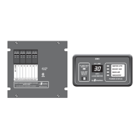
30 Amp Smart EMS Control Module
Display Panel Distribution Panel.
Control Module
30A SMART EMS
30A SMART EMS
30A SMART EMS
30A SMART EMS
The utilizes Intellitec’s RV Multiplex/PMC (Programmable Multiplex Control)
System as the communications link between the and the As an additional
diagnostic feature, the system includes two Communications Status LED’s on the Control Module. In normal
operation, when the is configured in the Stand-Alone Mode, or as the RV Multiplex Master, the
green “IPX OK” LED should be lit and the red “IPX Fail” LED should not be lit. Utilizing the RV Multiplex/PMC system,
the Smart EMS System can:
1) Operate as a Stand-Alone System.
2) Operate as an RV Multiplex System Master in an RV Multiplex System - allowing other devices such as
inverter/converters, input and output modules, and switch panels, to communicate with each other and the
Smart EMS System.
3) Operate as an PMC Transceiver with the addition of a PMC Central Processing Unit (CPU).
the average current entering the main circuit breaker over a three-hour period
TM
TM
TM
TM
TM
HOW IT WORKS
The provides main and branch circuit protection control of up to four selected appliances.
The control helps to limit the total current draw of all the appliances in the R , at or below 30 Amps provided by the
main power feed.
Circuit protection for ALL the 120 VAC loads is offered by standard, reset-able circuit breakers, provided by the
installer. There are four positions available for circuit breakers. These may be single, or dual units. One of these
breakers must be a 30 Amp unit to act as the Main breaker for the entire system. The 120 volt power is brought into
the box from either a shore cord, or generator. The line side of this cable is fed through the magnetically coupled
current transformer and connected to a 30 Amp circuit breaker that acts as the Main breaker. This breaker back-
feeds power into the circuit breaker bus to feed power to the branch breakers. These can be either single, or dual
circuit types. All the loads in the RV are fed from the branch breakers.
The current entering the main circuit breaker is routed through the magnetically coupled current sensor. This sensor
The RVIA (Recreational Vehicle Industry Association), in conjunction with the NEC (National Electrical Code),
require that a vehicle with 30 Amp service be equipped with a maximum of five 15 or 20 Amp circuit breakers unless
an energy management system is used. As a result, using the allows the use of two additional
breakers, enabling the vehicle to be equipped with additional circuits. It is also required that the energy management
system must limit the average current entering the main circuit breaker over a three-hour period to 80% of the 20 or
30 Amp service rating. Therefore, if
exceeds 80% of 30 Amps (24 Amps) when 30Aservice is selected, or 80% of 20 Amps (16 Amps) when 20Aservice is
selected, the will automatically change the service limit to 80% of the selected service.
Correspondingly, the will restore the service limit to the full 30 or 20 Amp value when the average
current drops below 80% of the service rating. When the lowered service limits are enabled as a result of average
current exceeding 80% of the service rating, the decimal point in the lower right-hand corner of the Load Meter on the
Display Module will be lit.
In addition, the has the capability of using the energy management feature when
the gen-set is the power source, preventing gen-set circuit breaker tripping and overload. The Control Module can
be configured by the installer to enable this feature using the configuration dip-switch (See Page 4).
30A SMART EMS
CIRCUIT PROTECTION
ENERGY MANAGEMENT WITH THREE-HOUR AVERAGING
Model 500A
TM
and
V
measures the current flowing through the main breaker, which is the total amount being drawn by all the 120 volt
appliances in the RV. When this current exceeds 30 Amps (20 Amps if that service type has been selected), the EMS will
turn off the controlled loads in an effort to bring the total current to the limit of the incoming service.
 Loading...