1485 Jacobs Rd.
Deland, FL 32724
386.738.7307
P/N 53-00912-000 Rev. D 080919
www.intellitec.com
Intellitec
INSTALLATION & SERVICE MANUAL
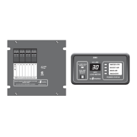
30A SMART ENERGY MANAGEMENT SYSTEM
TM
MODEL 500A
The 12 VDC voltage connections are made through J2, a 3 pin Mate-N-Lok connector on the low voltage side of
the control module. The +12 volts should be supplied from a source fused at 3 Amps minimum and capable of
delivering up to 1 Amp of AVERAGE current. Protecting this connection with a higher rated fuse is acceptable,
since the EMS is internally protected with a 3 Amp fuse.
1 + 12 Volts
2 Gen Set Run Input
3 Ground
The low voltage controlled load connections are made through J4, a 6 pin Mate-N-Lok connector on the low voltage
side of the control module.
1 Relay 5 Normally Open
2 Relay 5 Common
3 Relay 5 Normally Closed
4 Relay 6 Common
5 Relay 6 Normally Closed
6 Relay 6 Normally Open
The low voltage controlled load relay connections are typically made to the thermostat wires of the air conditioners.
The Normally Open contacts are wired in "series" with the thermostat. This means that the thermostat wire is cut and
the two ends are wired to the Common and the Normally Open contacts of the relay/s. In this way, the EMS can
interrupt the operation of the compressor, just as the thermostat does. The low voltage wires are brought into the box
through the large hole in the lower right-hand corner of the back of the box.
1) If only the compressors of the front and rearA/C's are to be controlled, connections are typically made to the low
voltage compressor control wires of the air conditioners. The normally closed contacts are wired in "series" with
the compressor control lead. This means that the compressor control wire is cut and the two ends are wired to the
Common and the Normally Closed contacts of Relay 5 or 6. In this way, the EMS can interrupt the operation of the
compressor, just as the thermostat does.
2) If both the compressors and fans of the front and rear A/C's are to be controlled, connections are typically made to
the low voltage thermostat control wires of the air conditioners. The Normally Closed contacts are wired in
"series" with each thermostat control lead. This means that the thermostat control wire is cut and the two ends are
wired to the Common and the Normally Closed contacts of Relay 5, or 6. In this way, the EMS can interrupt the
operation of the compressor and fans, just as the thermostat does.
3) If the compressor and fan for one of the A/C systems are to be controlled individually, connections are typically
made to the individual low voltage thermostat control wires for the fan and compressor of the air conditioner. The
Relay 6 connections are typically made to the low voltage compressor control wires of the air conditioner to
control the compressor. The normally closed contacts are wired in "series" with the compressor control lead.
This means that the low voltage compressor control wire is cut and the two ends are wired to the Common and the
Normally Closed contacts on Relay 6. The Relay 5 connections are typically made to the low voltage thermostat
control wires of the air conditioner to control the fan. The normally closed contacts are wired in "series" with the
thermostat control lead. This means that the low voltage thermostat control wire is cut and the two ends are wired
to the Common and the Normally Closed contacts on Relay 5. In this way, the EMS can interrupt the operation of
the fan, just as the thermostat does.
The connections are as follows:
The connections are as follows:
J2 Pin Function
J4 Pin Function
There are several methods to utilize Relay 5 and 6 connections for controlling air conditioner systems with
the EMS:
 Loading...