1485 Jacobs Rd.
Deland, FL 32724
386.738.7307
P/N 53-00912-000 Rev. D 080919
www.intellitec.com
Intellitec
INSTALLATION & SERVICE MANUAL
30A SMART ENERGY MANAGEMENT SYSTEM
TM
MODEL 500A
PLACEMENT
The EMS should be installed in a convenient location where it can get air
circulation to keep it from over heating. There should be a minimum of 7" of
depth behind the mounting surface to provide enough room for the box and
wiring.
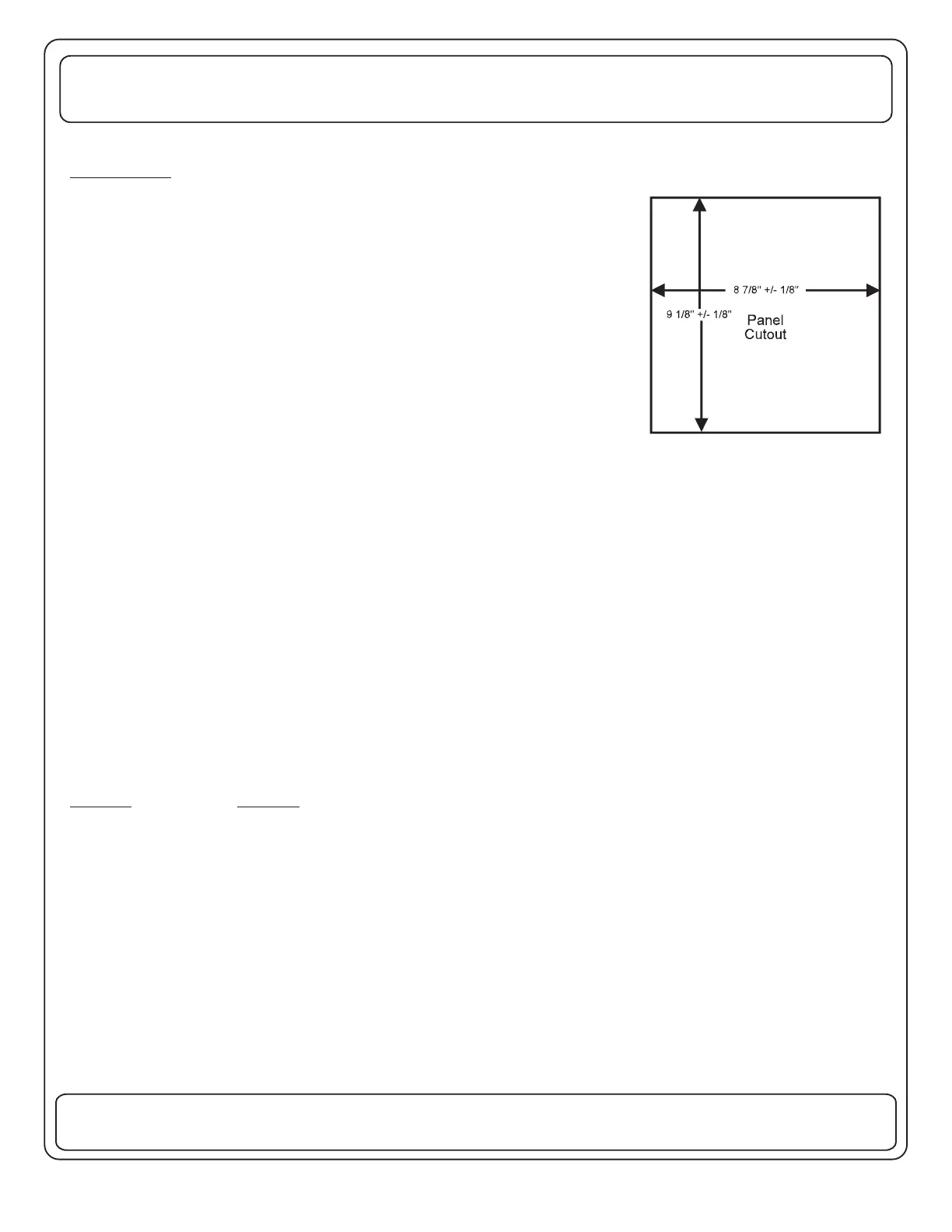
Ahole should be cut in the mounting panel as shown.
This opening must be cut carefully to be sure the mounting screws will have
enough wood to hold and that there is enough clearance around the box for
the front cover screws.
The wiring to the box should be routed through the holes in the back and
secured using approved cable connectors. The wires should be copper
conductors with the appropriate size and insulation to meet N.E.C.
The 10 gauge main cable should be brought through the large hole in the lower center of the box. The remaining
wires should be routed through the remaining holes in the back of the box.
The wires should be stripped and the ground wire of each cable connected to the GROUND bar, terminal strip. The
white or neutral wires should all be connected to the NEUTRAL bar terminal strip. Each terminal screw should be
tightened per the torque table on the front cover of the EMS.
If removed during installation, the white jumper wire should be re-installed between the NEUTRAL bar and J6,
terminal 5 of the EMS module. (See box drawing, page 6.)
The Black or "hot" lead should be routed through the hole in the current sensor and then to the screw terminal on the
30Amp Main breaker.
The black or "hot" leads of all the uncontrolled loads should be connected to their associated breakers.
To connect the 120 volt controlled loads, jumper wires should be connected from the respective circuit breakers to
the associated screw terminals on the EMS control module. The black wires to the controlled loads should be
connected to the proper screw terminals on the EMS module. Be sure these wires are under the screw terminals and
they are tightened to 14 +/-2 in.-lbs.
- 5 terminal block - Will accept up to 12 GA or 14 GA copper wire
5 Neutral
1 Output of Relay 3
2 From Circuit Breaker 3
ONLY,
J6 ONLY.
Terminal Function
1 From Circuit Breaker 2
2 Output of Relay 2
3 From Circuit Breaker 1
4 Output of Relay 1
- 2 Terminal Block Will accept up to 12 GA or 14 GA copper wire ONLY.J7
 Loading...