1
AMP SECTION
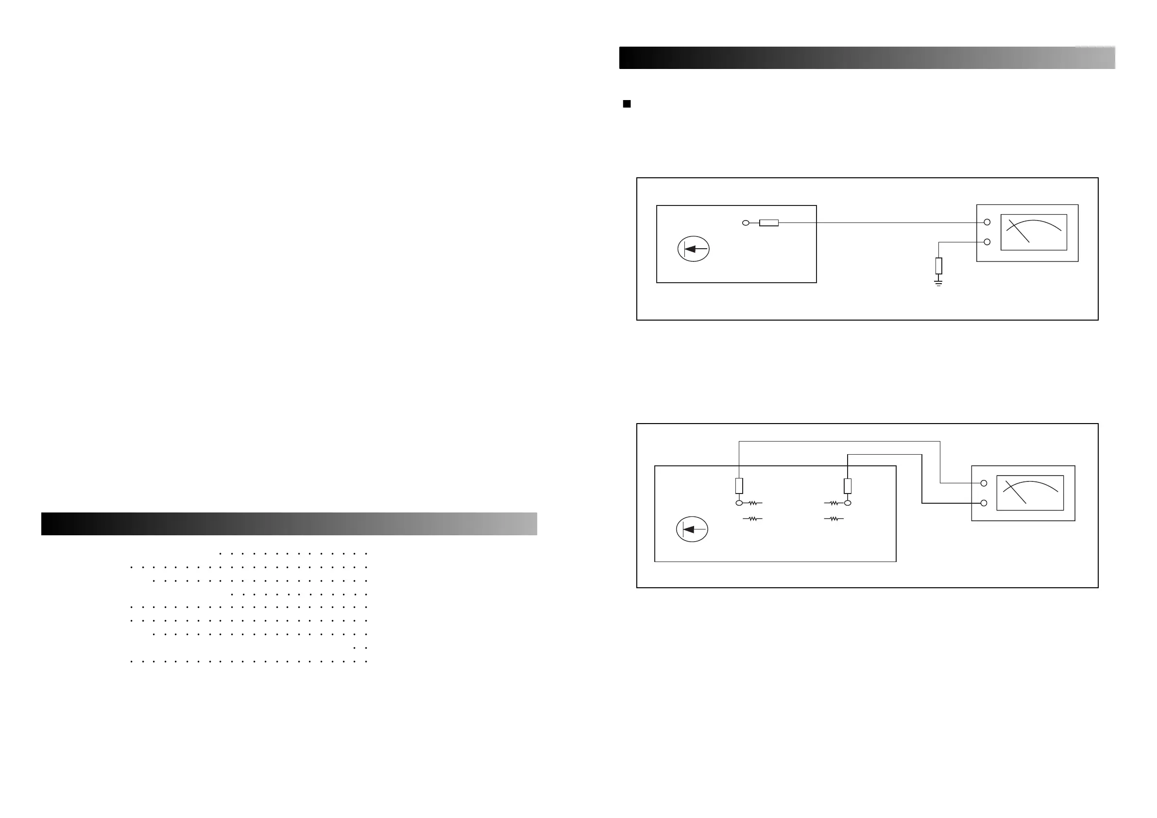
1. OFF SET VOLTAGE
A. Setting
Set the master volume control minimum.
B. Connection
C. Adjustment
Control OFFSET until voltmeter is the “0” position. (at Output Terminal)
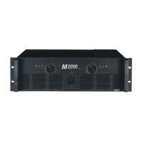
2. IDLE CURRENT
A. Setting
Set the master volume control minimum.
B. Connection
C. Adjustment
A-60: Adjust VR11 so that the current through the R56 and R58 become 10 milliampere. When that
voltage is 10 millivolt, the current becomes 10 milliampere.
A-120: Adjust VR11 so that the current through the R56 and R58 become 5 milliampere. When that
voltage is 5 millivolt, the current becomes 10 milliampere.
ELECTRICAL ADJUSTMENT PROCEDURE
Electrical Adjustment Procedure 1
Specifications
2
Electrical Parts List
3, 4
Top and Bottom View of P.C. Board
5
Wiring Diagram 6
Block Diagram 7
Schematic Diagram 8, 9
Exploded View of Cabinet & Chassis / Mechanical Parts List
10, 11
Ass’y Drawing
12, 13
CONTENTS