Do you have a question about the Inter-m LM-6414 and is the answer not in the manual?
Proper placement to maintain performance and service life. Environments include high heat, dust, moisture, vibration.
Essential guidelines for safe operation and handling of the equipment. Read, keep, heed all warnings, and follow instructions.
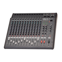
Details on fourteen channel inputs and multiple outputs for routing flexibility.
Describes the three-band equalization on all input channels for maximum control.
Details trim, peak indicators, and constant-level pan controls on each channel.
LED indicator for phantom power activation status at microphone inputs.
LED indicating when any of the Input Channel PFL switches are activated.
Activates +48VDC phantom power supply to all Input Channels.
LED meters displaying the output level as selected by the Output Monitor Selector.
Buttons to assign the channel's input signal to stereo or bus outputs.
Switch used to turn the unit on and off.
LEDs indicating when input signal is 3dB below clipping.
Knobs controlling input level for each associated input channel.
Controls for channel equalization and auxiliary signal routing.
Knobs controlling L/R balance and bus routing for channels.
Buttons used to monitor each channel's output status via headphones.
Knobs controlling the output level for each associated input channel.
Faders adjusting the output level of signals routed to Bus 1 and Bus 3.
Faders adjusting the output level of signals routed to Bus 2 and Bus 4.
Fader adjusting the output level of signals routed to the Master Bus.
Buttons selecting the associated output bus as active for monitoring.
Buttons selecting the output source for monitoring and headphones.
Balanced 1/4" stereo jack for headphone monitoring.
Knob controlling the output level of the headphone jack.
LED indicating when the unit is powered on.
Gain control for returned signal of AUX1/2 RETURN from external device.
PAN level controller for returned signal of AUX1/2 RETURN.
Selector for output level display modes (STEREO L/R, PFL, MON, Level).
Gain control for each input channel audio to send AUX1/2 SEND.
Connector for standard three-pin AC power cable and voltage selection.
Contains the AC overload protection fuse.
Line-level inputs via 1/4" phone and RCA connectors from various sources.
Mic-level inputs via balanced three-pin XLR connectors.
1/4" TRS jacks for input/output of external processor on stereo channels.
Line-level outputs for signal routed to the Stereo L/R output busses.
Line-level outputs for signal routed to the Monitor output busses.
Line-level outputs for signal routed to the Bus 1-4 output busses.
Terminals for connecting 24VDC battery power source.
Line-level inputs for connecting external effects processors.
1/4" TRS jacks for input/output of external processor on individual channels.
Line-level inputs via balanced 1/4" phone connectors.
Steps for problem diagnosis and contacting warranty provider.
Information on obtaining the circuit schematic.
Information on obtaining the parts list.
| Inputs | 6 XLR, 6 line |
|---|---|
| Outputs | Main L/R, 2 aux |
| THD | <0.1% |
| Signal to Noise Ratio | > 80dB |
| Dimensions | 482 x 44 x 200 mm |
| Weight | 2.5 kg |
| Type | Analog |
| Frequency Response | 20Hz - 20kHz |
| Power Supply | External PSU |
| Phantom Power | +48V (switchable on each mic channel) |
| Equalizer | 3-band EQ with sweepable mid (on each mic channel), 4-band EQ (on stereo channels) |