MIC LINE MIXER
8
LM-6414
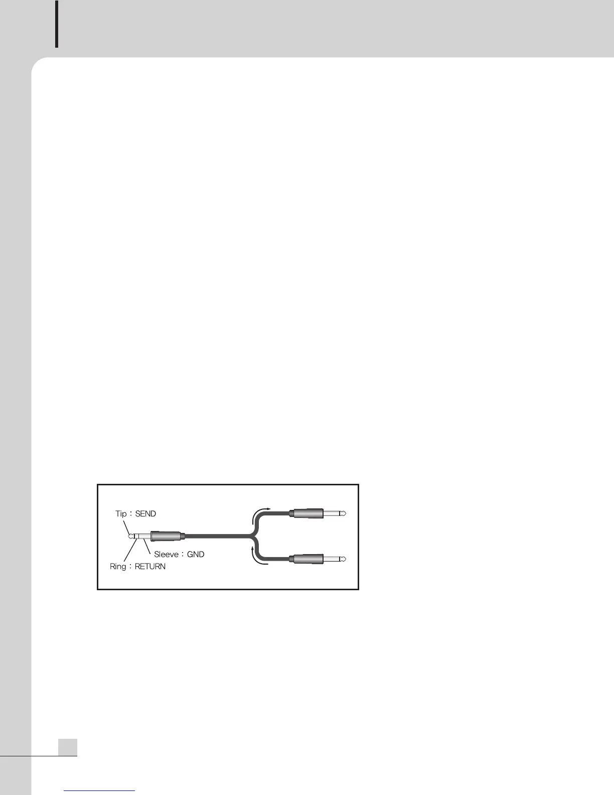
5. STEREO CHANNEL INSERT I/O
T
hese unbalanced 1/4” TRS jacks are provided for input and output of an external processor on the
individual stereo channel. The Insert signal is unaffected by the Channel Input levels.
6. STEREO OUTPUTS L/R
Line-level outputs on balanced 1/4” phone connectors. These are provided for output of signal routed to the
Stereo L/R output busses.
7. MONITOR OUTPUTS
Line-level outputs on balanced 1/4” phone connectors. These are provided for output of signal routed to the
Monitor output busses.
8. BUS OUTPUTS 1-4
Line-level outputs on balanced 1/4” phone connectors. These are provided for output of signal routed to the
Bus 1-4 output busses.
9. DC INPUT TERMINALS
These terminals are provided for the connection of DC battery power. Connect a 24VDC battery source to
these terminals. Make certain the red terminal is connected to the battery’s positive (+) side, and the black
terminal to the battery’s negative (–) side.
10. EFX SEND AND RETURN
Line-level inputs on unbalanced 1/4” phone connectors. These are provided for the connection of external
effects processors on the master buss.
11. CHANNEL INSERT I/O
These unbalanced 1/4” TRS jacks are provided for input and output of an external processor on the
individual channel. The Insert signal is unaffected by the Channel Input levels.
12. LINE INPUTS 1-6
Line-level inputs on balanced 1/4” phone connectors.